»щУЪPLLРЕәЕ·ўЙъЖчөДЙијЖ(ёҪіМРт,өзВ·Нј)
АҙФҙЈәwenku163.com ЧКБПұаәЕЈәWK16311909 ЧКБПөИј¶ЈәЎпЎпЎпЎпЎп %E8%B5%84%E6%96%99%E7%BC%96%E5%8F%B7%EF%BC%9AWK16311909
ЧКБПҪйЙЬ
»щУЪPLLРЕәЕ·ўЙъЖчөДЙијЖ(ёҪіМРт,өзВ·Нј)(ИООсКй,ҝӘМвұЁёж,ЦРЖЪұЁёж,НвОД·ӯТл,ВЫОД13000ЧЦ)
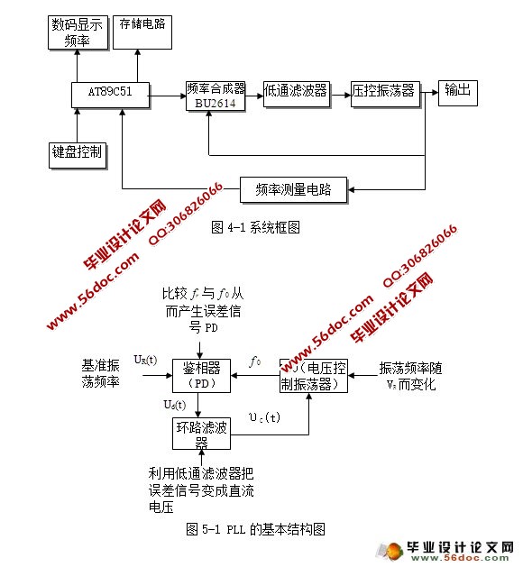
ХӘ ТӘ: ЛжЧЕОЮПЯНЁРЕјјКхөДУҰУГәН·ўХ№Ј¬¶ФёЯЦКБҝөДёЯЖөРЕәЕФҙТӘЗуИХТжЖИЗРЈ¬ХвЦчТӘұнПЦФЪ¶ФЖөВКөДОИ¶Ё¶ИәНЧјИ·¶ИөДТӘЗуФҪАҙФҪёЯЈ¬ІўЗТПЈНыДЬ·ҪұгөШөчХыЖөВКЎЈіЈјыөДРЕәЕІъЙъ·Ҫ·ЁәЬДСВъЧгХвР©ТӘЗуЈ¬ИзКҜУўҫ§МеХсөҙЖчҝЙТФҙпөҪәЬёЯөДЖөВКОИ¶Ё¶ИЈ¬ө«КЗөчХыЖөВКА§ДСЈ»LCХсөҙЖчөчХыЖөВКұИҪПИЭТЧЈ¬ө«КЗЖөВКОИ¶Ё¶ИәНҫ«¶И·ҪГжУЦҙпІ»өҪТӘЗуЎЈ¶шЛшПа»·ЖөВКәПіЙјјКхФтҝЙТФН¬КұВъЧгБҪ·ҪГжөДТӘЗуЎЈұҫЙијЖХэКЗ»щУЪХвЦЦјјКхАҙІъЙъХэПТІЁРЕәЕөДЈ¬НЁ№эөҘЖ¬»ъҝШЦЖЖөВКәПіЙЖчЈ¬ҙУ¶шҝШЦЖРЕәЕөДКдіцЖөВКЎЈОӘБЛұгУЪ№ЫІмЖөВКөДұд»ҜЈ¬УГКэВл№ЬјаІвКдіцЖөВКЦөІў°СөұЗ°ЦөЛНөҪҙжҙўЖчҙжҙўЎЈҙЛЙијЖөзВ·ҝЙТФІъЙъЖөВКОИ¶Ё¶ИЎўҫ«¶ИёЯөДХэПТІЁЎЈ
№ШјьҙКЈәЛшПа»· өҘЖ¬»ъ ҙжҙўЖч
The Design of Signal Generator Based on theЎЎPLL
Abstract: With the application and development of wireless communication, it is demands for signal sources with high-quality and high-frequency;it is not only mainly reflected in the frequency stability and accuracy but also in hoping that the frequency could be easily adjusted. However, it is difficult to meet these demands by the common way generating signal source. For example, although quartz crystal oscillator can reach high stability of frequency, the adjustments of frequency is inconvenience; LC oscillator frequency adjustment is very convenient, But the stability and accuracy of frequency can't meet requirement. Compared with the methods above. phase locked loop frequency synthetic technology can meet all various aspects demands. The design is based on this technology to generate sine wave signal, frequency synthesizers is controlled by the Single Chip Microcomputer and controls the output frequency. In order to make convenience to observe the change of frequency, the system uses LED to monitor the output frequency and then send it to the memory devices. This design can generate sine wave with high stability and precision frequency. Keyword: Phase locked loop Single Chip Microcomputer Memory
ЙијЖТӘЗу
АыУГЛшПа»·јјКхІъЙъТ»ёцК§Хж¶ИРЎЎўЖөВКҙУ30MHzөҪ100MHzөДҝЙөчөДХэПТІЁРЕәЕЎЈёщҫЭЖөВКөДІ»Н¬СЎФсІ»Н¬ІҪҪшөДұкЧјЖөВКЎЈөұРЕәЕҙҰУЪҪПөНЖөВККұЈ¬СЎФсІҪҪшОӘ1KHzөДұкЧјЖөВКЈ¬ҙЛКұЛьөДЧоРЎОуІоІ»ҙуУЪ0.8%Ј»өұРЕәЕФЪҪПёЯөДЖөВК¶ОКұЈ¬СЎФсТФ25 KHzОӘұкЧјЖөВКЈ¬ЛьөДЧоРЎОуІоІ»ҙуУЪ0. 5%ЎЈ
Дҝ Вј
1ТэСФ………………………………………………………………………………………1
2ЙијЖТӘЗу…………………………………………………………………………………1
3 ·Ҫ°ёВЫЦӨУлұИҪП…………………………………………………………………………1
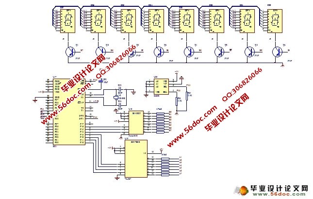
4 ПөНіЧйіЙ…………………………………………………………………………………2
5 ЛшПа»·ҪйЙЬ………………………………………………………………………………3
6өҘФӘөзВ·ЙијЖ……………………………………………………………………………5
6.1С№ҝШХсөҙЖч……………………………………………………………………………5
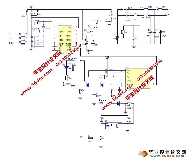
6.2 ЛшПа»·КҪЖөВКәПіЙЖчөДЙијЖ…………………………………………………………7
6.3өННЁВЛІЁЖч …………………………………………………………………………10
6.4өзФҙЗР»»өзВ·ЙијЖ …………………………………………………………………10
6.5 өзФҙөзВ·ЙијЖ………………………………………………………………………11
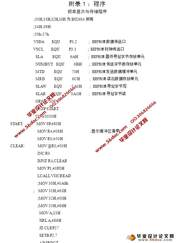
6.6 ҙжҙўөзВ·ЙијЖ………………………………………………………………………11
6.7 өзЧУҝШЦЖөҘФӘөзВ·ЈЁECUЈ©…………………………………………………………14
6.8 ЖөВКІвБҝПФКҫөзВ·…………………………………………………………………18
7 ИнјюЙијЖ………………………………………………………………………………19
8 ІвКФҪб№ы………………………………………………………………………………21
9 ҪбВЫ……………………………………………………………………………………22
ІОҝјОДПЧ…………………………………………………………………………………23
ЦВР»………………………………………………………………………………………24
ёҪВј1ЈәіМРт……………………………………………………………………………25
ёҪВј2ЈәЧЬөзВ·Нј………………………………………………………………………44
|
