反激式开关电源设计(附实物图,电路图,PCB图,元件清单)(任务书,开题报告,中期检查表,论文18000字)
摘要
随着我们科技的进步和通讯等高新产业的快速发展,我们的生活发生了翻天覆地的变化,一些与这些产业密切相关的技术也随之不断进步,开关电源技术就是其中一种。
本文对buck和boost等常见开关电源电路结构进行了对比,且对正激和反激式拓扑结构进行了比较,并从中选取了适合本设计的反激式的拓扑结构,还对电路关键器件变压器的各项参数进行了计算,然后选取VIPER22A芯片和PC817等主要元器件,并简述了它们的基本性能参数,最后对电路总体体设计方案进行阐述,最后对影响的开关电源性能的负载特性和纹波波特性加以测试,完成了本次的毕业设计。
反激式开关电源具有稳定性、可靠性、利用效率高等特点,而且由于反激式的特殊结构将输入和输出部分隔离开来,提高了抗干扰能力。因此本设计介绍了应用反激式拓扑结构的开关电源系统,并留下了改进的空间。
关键字:开关电源 拓扑结构 稳压管 viper22a芯片
Abstract
With the progress of our science and technology and communications and other high-tech industry's rapid development, great changes have taken place in our life, some have been closely related to the industry technology progress, switching power supply technology is one of them.
In this paper, the buck and the boost of common switching power supply circuit structure are compared, and the normal shock and flyback topology are compared, and choose the suitable for the design of the flyback type topological structure, is the key device of transformer circuit parameters are calculated, and then select VIPER22A chip and PC817 main components, and describes their fundamental performance parameter, finally to shed light on the circuit design of the whole body, finally, the influence of the performance of switch power supply to test the load characteristics and grain bobo, completed the graduation design.
With the flyback type switch power supply has the stability, reliability and high efficiency, and due to the special structure of the flyback type isolates the input and output part, improve the anti-interference ability. This design introduces the application of the flyback type topology structure of switch power supply system, and left the room for improvement.
Keywords: Switching Powersupply Topological Structure Regulator Viper22achip
目录
1 绪论 1
1.1 开关电源的产生 1
1.1.1 开关电源产生的时代背景 1
1.1.2 开关电源的产生 1
1.2 开关电源的发展 2
1.2.1 国内的开关电源的发展 2
1.2.2 国外开关电源的发展 3
1.3 开关电源的现状 3
2 开关电源的几种结构 4
2.1 boost电路 4
2.2 buck电路的工作原理及特点 5
2.3 正激电路的工作原理及特点 7
2.4 反激电路的工作原理 9
3 电路的选择 11
3.1 电路拓扑类型的选择 11
3.1.1 电路拓扑结构选择要注意的问题 11
3.1.2 拓扑结构的对比分析 11
3.2 反激变压器的主要方程 13
3.3 变压器磁芯的选择和匝数的计算 14
3.3.1 变压器的磁芯的选择 14
3.3.2 变压器的匝数计算 15
3.3.3 磁芯等的各种损耗 16
4 开关电源设计中元件的选取 17
4.1 VIPER22A的管脚图及其作用 18
4.2 pc817的管脚图和封装图 18
4.2.1 pc817 的特点和应用 18
4.2.2 pc817 最大绝对值和观点特性 19
4.3 肖特基二极管的外观及结构 20
5 硬件电路设计 23
5.1 整流滤波电路设计 23
5.1.1 抑制开关电源产生的干扰 27
5.2 直流-直流的电路设计 29
6 测试分析 31
6.1 负载特性测试 31
6.2 纹波特性测试 32
结论 34
致谢 36
参考文献 37
附录 37
附录A元件清单 38
附录B PCB图 39
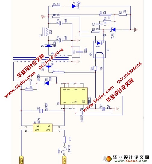
附录C总电路图 40
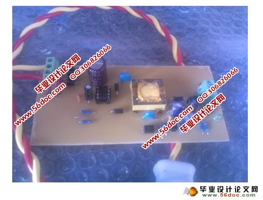
附录D实物图 41
|
