摘 要
数控机床作为机电一体化的典型产品,在机械制造业中发挥着巨大的作用,很好地解决了现代机械制造中结构复杂、精密、批量小、多变零件的加工问题,且能稳定产品的加工质量,大幅度地提高生产效率。但从目前企业面临的情况看,因数控机床价格较贵,一次性投资较大使企业心有余而力不足。我国作为机床大国,对普通机床数控化改造不失为一种较好的良策,对普通机车进行数控化改造可大大提高原有机车的自动化程度与生产率成本仅为全功能数控机场的1/3~1/4。(毕业设计网 )
本文主要介绍了采用单片机系统加上步进电机驱动系统组成简易的机床计算机数控柜以取代原有的硬件数控柜或用于改造普通机床。首先阐明了数控系统总体方案设计同时给出了总体装配图,随后着重介绍了机床进给系统的机械部分设计和计算和相应的图纸,控制系统利用微机对纵、横向系统开环控制,驱动元件采用直流步进电机,传动系统采用滚珠丝杆,用单片机8031控机床进给系统的硬件组成及MGLS240128T驱动LCD的显示和整个的硬件设计进行分析,并对相应电路设计进行相关的阐述,接下来介绍下数控机床零件加工程序。
关键词: 微机;数控;步进电机;单片机;滚珠丝杆
Enters with the microcomputer numerical control
technological transformations biggest processing diameter 320 millimeter conventional lathe for the system
Abstract
The numerical control engine bed took the integration of machinery the typical product, is playing the huge role in the mechanical manufacturing industry, solved in well the modern machine manufacture the structure complex, precise, the batch has been small, the changeable components processing question, also could stabilize the product processing quality, large scale enhanced the production efficiency. But the situation which faces from the present enterprise looked, because the numerical control engine bed price is expensive, the disposable investment compares ambassador the enterprise to have more desire than energy. Our country took the engine bed great nation, does not lose to the ordinary engine bed numerical control transformation is one good brilliant plan, carries on the numerical control transformation to the ordinary locomotive to be possible to enhance the original locomotive the automaticity and the productivity cost only is greatly the entire function numerical control airport 1/3 ~ 1/4.
This article mainly introduced uses the monolithic integrated circuit system to add on step-by-steps the motor-driven system composition simple engine bed computer numerical control cabinet by to substitute for the original hardware numerical control cabinet or to use in transforming the ordinary engine bed. First had expounded at the same time the numerical control system overall plan design has produced the overall assembly drawing, afterwards introduced emphatically the engine bed enters for the system machine part design and the computation and the corresponding blueprint, the control system use microcomputer to vertical, the crosswise system open-loop control, actuates the part to use direct current to step-by-step the electrical machinery, the transmission system uses the ball bearing lead screw, 8,031 controls the engine bed with the monolithic integrated circuit to enter actuates LCD for the system hardware composition and MGLS240128T the demonstration and the entire hardware design carries on the analysis, and carries on the correlation to the corresponding circuit design the elaboration, meets down under the introduction the numerical control engine bed components processing procedure.
Key words: Microcomputer; Numerical control; Step-by-steps the electrical machinery; Monolithic integrated circuit; Ball bearing lead screw
总体方案设计内容
数控改造,必须首先拟定总体方案,绘制系统总统框图,才能觉得各种设计参数和结构,然后再分别对机械部分和电气部分进行计算。
(一)系统运动方案的确定
数控系统按运动方式可分为定位控制系统、点位直线控制系统和连续控制系统。
1.控制方式选择
伺服系统可分为开环控制系统,半闭环控制系统。
开环控制系统中,没有检测反馈装置,数控装置发出的信号的流程是单向的,也正是由于信号的单向流程,它对机床移动部件的实际位置不做检测,所以机床加工精度要求不太高,其精度主要取决于伺服系统的性能。开环伺服系统主要是由步进电机驱动。这类机床工作比较稳定,反映迅速,调试和维修比较简单。目前经济型数控机床普通采用开环伺服系统。
半闭环控制系统中,对工作台的实际位置不进行检查测量,而是通过与伺服电机有联系的测量元件,如测速发电机或光电编码盘等间接测出伺服电机的转角,推算出工作台的实际位置量,用此值与指令植进行比较,用差值来实现控制。这种控制方式介于开环与闭环之间,精度没有闭环高,调试却比比环方便。
闭环控制系统有机床移动部件上的检测反馈装置,在加工时刻检测机床移动部件的位置,使之和数控装置所要求的位置想符合,以期达到很高的加工精度。闭环系统多采用直流伺服电机或交流电机驱动。这类机床的优点是精度高,速度快,但是调试个维修比较复杂,其关键是系统的稳定性,所以在设计是必须对稳定性给予足够的重视。
总体方案的确定
1.系统运动方式与伺服系统的选择
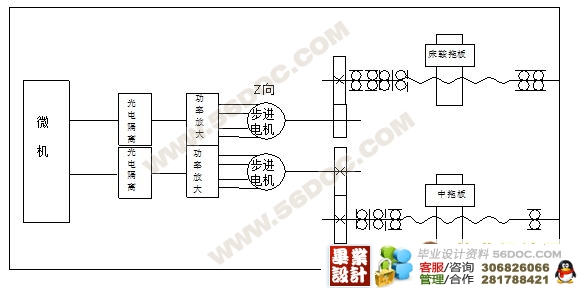
由于改造后的经济型数控车床具有定位、直线插补、顺、逆圆弧插补、暂停、循环加工、公英制螺纹加工等功能,故应选择连续控制系统。考虑属于经济型数控机床加工的精度要求不高,为了简化结构、降低成本,采用步进电机开环控制系统。
2.数控系统
根据机床要求采用8为微机。由于MCS—51系列单片机具有集成度高,可靠性好,功能强,速度快。抗干扰性强,具有很高的性能价格比等特点,决定采用MCS—51系列的8031单片机扩展系统。
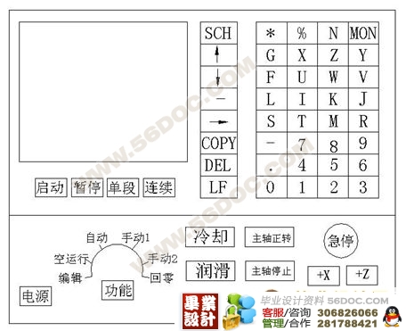
控制系统由微机部分、键盘和显示器、I/O接口及发光隔离电路、步进电机功率放大电路组成,系统的加工程序和控制命令通过键盘操作实现,显示器采用数码管显示加工数据及机床状态等信息。(毕业设计网 )
3.机械传动方式
为了实现 机床所要的分辨率,采用步进电机经齿轮减速传动丝杆,为保证一定的传动精度和平稳性,尽量减少摩擦力,选用滚珠丝杆螺母副。同时,为了提高传动刚度和消除间隙,采用有预加负荷的结构。齿轮传动也要采用消除齿侧间隙的结构。


目 录
摘要 ……………………………………………………………………………………………
Abstract ………………………………………………………………………………………
第一章 数控机床系统总统设计方案拟定 ……………………………………………………
1.1 总体方案设计内容 ……………………………………………………………………
第二章 机床进给系统机械部分设计计算 ……………………………………………………
2.1 确定系统脉冲量 …………………………………………………………………………
2.2 切削力计算 ………………………………………………………………………………
2.3 滚珠丝杆螺母副 …………………………………………………………………………
2.4 齿轮传动计算 ……………………………………………………………………………
2.5 步进电机的计算和选型 …………………………………………………………………
2.6 进给系统机械部分的结构计算 …………………………………………………………
第三章 微机数控机床系统的设计 ……………………………………………………………
3.1 微机数空系统的设计内容 ……………………………………………………………
3.2 硬件控制电路设计 ……………………………………………………………………
3.3 机床数控系统软件设计 …………………………………………………………………
(毕业设计网 )
第四章 数空机床零件加工程序 …………………………………………………………………
4.1 数控工艺性分析和加工路线的确定 …………………………………………………
4.2 数控机床的选型 ………………………………………………………………………
4.3 零件加工程序 ……………………………………………………………………………
结束语 ……………………………………………………………………………………………
参考文献 …………………………………………………………………………………………
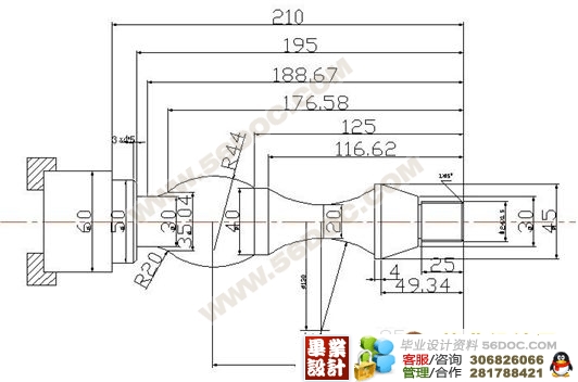
数控编程(部分)
N001 G90
N002 G92 X200 Z110
N003 M03 S700
N004 M06 T3
N005 G00 X28 Z2
N006 G00 X18 Z
N007 G01 X24 Z - 1 F30
N008 G01 X Z - 24. 5 F
N009 G01 X30 Z F
N010 G01 X45 Z - 45 F
N011 G01 X Z - 50. 09 F
N012 G03 X40 Z - 116. 2 F30 I130 K- 85
N013 G01 X Z - 125 F
N014 G02 X35. 6Z - 176. 59 F I - 20 K- 150
N015 G03 X30 Z - 188. 67 F I70 K- 188. 67
N016 G01 X Z - 195 F
N017 G01 X44 Z F
N018 G01 X50 Z - 198 F
N019 G01 X Z - 210 F
N020 G01 X60 Z F
N021 G00 X200 Z110
.... |


