ЛљгкЕЅЦЌЛњЕФЪ§зжжгЩшМЦ(ИНГЬађ,ЕчТЗЭМ)
РДдДЃКwenku163.com зЪСЯБрКХЃКWK16311822 зЪСЯЕШМЖЃКЁяЁяЁяЁяЁя %E8%B5%84%E6%96%99%E7%BC%96%E5%8F%B7%EF%BC%9AWK16311822
зЪСЯНщЩм
ЛљгкЕЅЦЌЛњЕФЪ§зжжгЩшМЦ(ИНГЬађ,ЕчТЗЭМ)(ЭтЮФЗвы,ТлЮФ19000зж)
The design of digital clock based on signal-chip computer
еЊ вЊ
ЛљгкЕЅЦЌЛњЕФЖЈЪБКЭПижЦзАжУдкаэЖраавЕгазХЙуЗКЕФгІгУЃЌЖјЪ§зжжгЪЧЦфжазюЛљБОЕФЃЌвВЪЧзюОпгаДњБэадЕФвЛИіР§згЁЃ
дкЛљгкЕЅЦЌЛњЯЕЭГЕФЪ§зжжгЕчТЗжаЃЌГ§СЫЛљБОЕФЕЅЦЌЛњЯЕЭГКЭЭтЮЇЕчТЗЭтЃЌЛЙашвЊЭтВПЕФПижЦКЭЯдЪОзАжУЁЃБОЕчТЗжївЊвдЕЅЦЌЛњAT89S52ЮЊКЫаФЖјЩшМЦЕФЃЌЭЈЙ§ЕЅЦЌЛњЖдаХЯЂЕФЗжЮігыДІРэЃЌПижЦЭтЮЇЩшБИЁЃЯЕЭГгЩИДЮЛФЃПщЁЂЪБжгФЃПщЁЂЮТЖШФЃПщЁЂвєРжФЃПщЁЂЙтЪЖФЃПщМАЯдЪОФЃПщЙВСљИіФЃПщзщГЩЃЌКѓРДдкЪБжгФЃПщЕФЛљДЁЩЯгжМгдиСЫШеРњЁЂаЧЦкЕФФЃПщЁЃ
БОЩшМЦвдЕЅЦЌЛњAT89S52ЮЊЧаШыЕуЃЌЭЈЙ§ЪЙгУAT89S52ЕФФкВПЕФПЩБрГЬЖЈЪБЦї/МЦЪ§ЦїЃЌНсКЯЖдЭтНгОЇеёЕФЕїНкРДШЗЖЈвЛИіКЯЪЪЕФеёЕДжмЦкЃЌДгЖјШЗЖЈГіФкВПЕФЛњЦїжмЦкЁЃдйЭЈЙ§ЖдФкВПжаЖЯГЬађЕФЩшжУРДЩшМЦГіЪБжгГЬађЃЌМДЩшМЦГіСЫЕчзгЪБжгЕФКЫаФЁЃШЛКѓдкКЫаФЕчТЗЕФЛљДЁЩЯЩшМЦГіСЫЯргІЕФРЉеЙЕчТЗЃЌЪЙБОЩшМЦИќМгЪЕгУЁЃ
ЙиМќДЪЃКЕЅЦЌЛњЃЛЪ§ТыЯдЪОЃЛЮТЖШДЋИаЦї
ABSTRACT
The timer equipment using micro controller unit is applied in many trades, the digital clock is the most fundamental example among them, and it is also a most typical example.
In digital clock circuit based micro controller unit system, there are the external controlling and display device besides the fundamental monolithic machine system and the outer-ring circuit. The key of the circuit in this design is AT89S52, using the micro control system to process information to control the outer-ring circuit. The system is made up of circuit, clock circuit, music circuit, temperature circuit, and shine circuit. Date and week modul is the external part.
This design focuses on monolithic integrated circuit AT89S52. Using AT89S52, which has the interior programmable timer/counter, the union foreign meets the crystal oscillator the adjustment to determine an appropriate duration of oscillation, thus determines theinterior the cycle of the system. And designing the internal interrupt procedure establishment to design the clock procedure, namely designed the core of electronic clock. Then design the expanded electric circuit to let this design more practical.
Key WordsЃКMicro control unit; LED shows; Sensor of temperature
ФП ТМ
1. в§бд 1
2. ЙигкЕЅЦЌЛњ 2
2.1ЕЅЦЌЛњЕФЗЂеЙ 2
2.2 ЕЅЦЌЛњЕФПЊЗЂБГОА 4
2.2 ЕЅЦЌЛњЕФПЊЗЂБГОА 5
2.3 AT89S52ЕЅЦЌЛњ 6
2.3.1 AT89S52ЕЅЦЌЛњв§НХЙІФм 7
2.3.2 AT89S52ЕЅЦЌЛњгВМўНсЙЙЕФЬиЕу 8
2.3.3 AT89S52ЕЅЦЌЛњЕФгВМўдРэ 10
3. ЗНАИЩшМЦгыТлжЄ 12
4. ЯЕЭГзмЬхНсЙЙПђЭМ 13
5. ЯЕЭГЕФгВМўЩшМЦ 14
5.1 ЯдЪОВПЗжЕчТЗЕФЩшМЦ 14
5.1.1 LEDЪ§ТыЯдЪОЙмЕФЛљБОдРэ 14
5.1.2 Ъ§ТыЙмЯдЪОФЃПщЗжЮі 14
5.1.3 LEDЯдЪОЕчТЗ 15
5.2 ПижЦВПЗжЕчТЗЕФЩшМЦ 15
5.2.1 ЪБжгФЃПщ 15
5.2.2 ЮТЖШФЃПщ 16
5.2.3 вєРжФЃПщ 16
5.2.4 ИДЮЛФЃПщ 16
5.2.5 ЙтЪЖФЃПщ 17
6. ЯЕЭГЕФШэМўЩшМЦ 18
6.1 ИїФЃПщЕФГЬађЩшМЦ 18
6.1.1 МЦЪБГЬађ 18
6.1.2 ЖЈЪБФжжгГЬађ 18
6.1.3 ЮТЖШГЬађ 18
6.2 ЯЕЭГГЬађЩшМЦЕФзмЬхПђЭМ 19
7. ЯЕЭГЕчТЗЕФжЦзїгыЕїЪд 20
7.1 ЕчТЗгВМўКИНгжЦзї 20
7.2 ЕїЪдЕФжївЊЗНЗЈ 20
7.3 ЯЕЭГЕїЪд 20
7.3.1 гВМўЕїЪд 20
7.3.2 ШэМўЕїЪд 20
7.3.3 СЊЛњЕїЪд 21
7.3.4ЕїЪджагіЕНЕФЮЪЬтМАНтОіЗНЗЈ 21
НсТл 23
ВЮПМЮФЯз 24
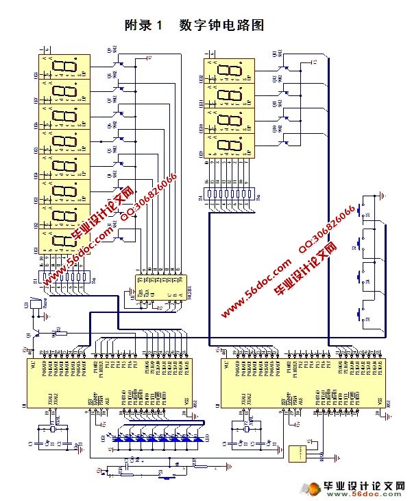
ИНТМ1 Ъ§зжжгЕчТЗЭМ 26
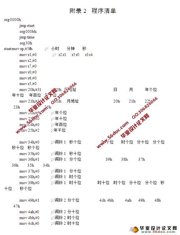
ИНТМ2 ГЬађЧхЕЅ 27
ИНТМ3 гЂЮФзЪСЯ 59
ИНТМ4 гЂЮФзЪСЯЗвы 69
жТаЛ 77
|
