篮球比赛计时器的设计
来源:wenku163.com 资料编号:WK1638035 资料等级:★★★★★ %E8%B5%84%E6%96%99%E7%BC%96%E5%8F%B7%EF%BC%9AWK1638035
资料介绍
摘要
本文主要介绍:篮球比赛计时器。本文首先介绍单片机的相关知识,对单片机进行相应的研究,并将其与74HC595串行显示电路配合使用。本电路主要核心是AT89S51,利用软件和硬件的结合实现开机自动置节计数器为第一节,节计时器为12分00秒,24秒违例为24秒。用数字显示篮球比赛当时节数,每节时间及24秒的倒计时,采用单片机串行显示。最后,本文会详细叙述此电路的安装与调试,并对调试过程中出现的问题做简要说明。
关键词 AT89S52单片机;74HC595;XXX
Abstract
Abstract this article mainly introduced: Basketball game timer. This article first introduced that monolithic integrated circuit's related knowledge, conducts the corresponding research to the monolithic integrated circuit, and its and 74HC595 serial display circuit coordination use. This electric circuit main core is AT89S51, realizes using the software and hardware's union starting sets at the festival counter for first, the festival timer is 12 minute 00 second automatically, 24 second case of breaching the rules is 24 seconds. With the digital demonstration basketball game at that time the pitch number, each time and 24 second countdown, used the monolithic integrated circuit serial demonstration. Finally, this article will narrate this electric circuit's installment and the debugging in detail, and to will debug the question which in the process will appear to give the briefing。
key words 89S52 monolithic integrated circuit; 74HC595; XXX
目 录
摘要 I
ABSTRACT II
第1章 绪论 1
1.1 课题背景 1
1.2 设计简介 2
第2章 系统电路的设计方案 3
2.1 系统设计方案的提出 3
2.2 方案的确定 3
2.3 本章小结 3
第3 章 电路设计原理及芯片介绍 4
3.1 键盘控制及显示电路设计的原理及要求 4
3.1.1 电路的设计原理与功能要求 4
3.1.2 电路的总设计框图 4
3.2 总电路选用芯片简介 4
3.2.1 控制芯片AT89S52 4
3.3 LED显示原理介绍 11
3.4 键盘控制原理介绍 14
3.4.1 键盘的工作原理 14
3.4.2 独立式键盘 17
3.5 本章小结 20
第4章 键盘控制及显示硬件电路实现 21
4.1 LED显示电路设计 21
4.2 独立按键键盘的电路设计 22
4.3 硬件的焊接 23
4.3.1 硬件的焊接 23
4.3.2 电路板的检查和故障排除 24
4.4 本章小结 24
第5 章 键盘控制及显示电路软件设计 26
5.1 软件设计的基本工具 26
5.1.1 汇编语言的简介 26
5.1.2 汇编语言的指令系统与程序 26
5.1.3 keilC51开发软件简介 28
5.2 独立式键盘软件设计 28
5.2.1 软件设计流程图 29
5.3 键盘控制及显示电路设计软件实现总流程图 29
5.3.1 总流程图 29
5.4 本章小结 30
结 论 31
致 谢 32
参考文献 33
附录1 外文资料 34
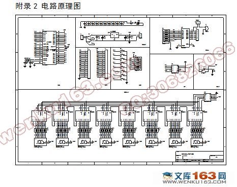
附录2 电路原理图 37
附录3 汇编源程序 38
附录4 元件清单 45
附录4 元件清单
序号 名称 代号 规格型号 数量(个)
1 单片机 U1 AT89S52 1
2 驱动器 U2 ULN2003 1
3 锁存器 U3-U10 74HC595 8
4 稳压块 LM1 7805 1
5 数码管 LED1-LED8 SEG0.5 8
6 电解电容 C13、C14 100uF 2
7 电解电容 C17 10uF 1
8 瓷片电容 C1-C12 104 12
9 瓷片电容 C15-C16 30P 2
10 SIP8电阻 R3、R4 4.7K 2
11 自锁开关 S1 6*6 1
12 按键 S2-S10 4*4 9
13 电阻 R1 4.7K 1
14 电阻 R2 1K 1
15 电阻 R5 10K 1
16 插针 J1-J2 2PIN 2
17 插针 J3-J5 20PIN 3
18 插针 J6 7PIN 1
19 晶阵 L1 12M 1
20 蜂鸣器 B1 @10 1
|