轿车双横臂悬架的设计(含CAD图)(任务书,开题报告,外文翻译,论文说明书9800字,CAD图纸3张)
摘要
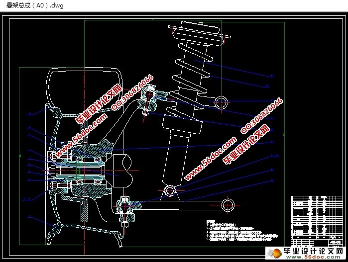
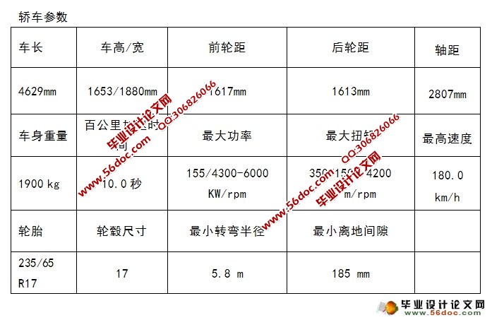
双横臂式独立悬架是一种常见的汽车悬架,由于工作性能好且稳定可靠,许多汽车,尤其是高档轿车,使用了这种悬架。该悬架可以通过改变导向杆系的接触点的位置及控制臂的长度,使得悬架得到良好的的运动特性。尤其是采用上下横臂不等长的结构可以延长轮胎的使用寿命,能够提高汽车行驶平顺性和操纵稳定性。本次设计的是不等长横臂的双横臂式独立悬架悬架。在设计时,首先根据汽车参数,计算悬架的主要参数;接着设计导向机构,分析如何计算得到侧倾中心和纵倾中心,合理设计悬架的布置方案,并分析上下横臂长度的比值对汽车的影响,参考已有车型数据设计了上下横臂的长度;接着参照各种要求和之前计算的的数据设计了螺旋弹簧并校核合格;然后按照标准和之前的数据选择了减震器,最后通过CAD完成图形的绘制。
关键词: 汽车; 双横臂独立悬架; 螺旋弹簧; 减振器
Design of double wish-bone suspension of car
Abstract
Double wish-bone independent suspension is a common vehicle suspension, because the work is stable and reliable, is widely used in the car, especially the luxury car. Through the reasonable selection of the position of the contact point and the length of the control arm of the guide bar, the suspension can have reasonable movement characteristics. Especially, the use of the upper and lower cross arm structure can extend the service life of the tire, can improve the ride comfort and handling stability of the car. This object of design is unequal length double wish-bone suspension. In the design, first of all,according to the vehicle parameters, main parameters for calculation of suspension; and guiding mechanism were designed, analysis how to calculate get roll center and pitch center, design the reasonable layout of suspension, and Analysis on cross arm length ratio of vehicle impact, reference has been design data model on lower cross arm length; then according to various requirements and calculation data of the design of the spiral spring and checking of qualified; then in accordance with the standards and before the data choose shock absorber. Finally, draw graphics though software CAD .
Key words: Automotive; Double wish-bone independent suspension; Coil spring; Shock absorber
目 录
摘要 III
Abstract IV
第1章 绪论 1
1.1 设计的背景和目的 1
1.2 主要任务和要求 1
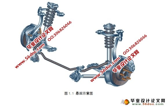
1.3 悬架的结构 1
1.4 双横臂式独立悬架 2
1.5 悬架的设计要求 3
第2章 悬架主要参数的确定 4
2.1 研究的轿车参数 4
2.2 悬架静挠度的计算 4
2.3 悬架动挠度的计算 5
2.4 悬架的弹性特性 5
2.5 小结 6
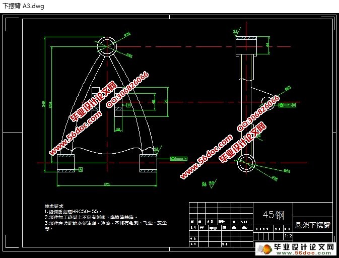
第3章 悬架导向机构的设计 7
3.1 设计的要求 7
3.2 导向机构的设计参数 7
3.2.1 侧倾中心 7
3.2.2 侧倾轴线 8
3.2.3 纵倾中心 8
3.3 导向机构的布置 8
3.3.1 纵向平面内上下横臂的布置方案 8
3.3.2 横向平面内的上下横臂的布置方案 9
3.3.3 水平面内上下横臂轴的布置方案 10
3.3.4 上下横臂长度的确定 11
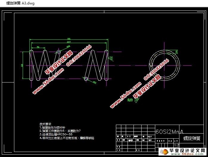
第4章 螺旋弹簧的设计 13
4.1 螺旋弹簧材料的选择 13
4.2 螺旋弹簧几何参数的选择 13
4.2.1 弹簧所受压力 13
4.2.2 弹簧刚度的计算 13
4.2.3 计算弹簧钢丝的几何参数 14
4.3 弹簧的校核 15
4.3.1 弹簧的刚度校核计算 15
4.3.2 弹簧的剪切应力校核 15
4.4 计算结果及小结 16
第五章 减振器的选择 17
5.1 减震器的类型 17
5.2 双筒式液力减振器的结构及工作原理 17
5.3 相对阻尼系数的确定 19
5.4 阻尼系数的确定 19
5.5 最大卸荷力V_x的确定 20
5.6 减振器工作缸直径的确定 20
小结 22
参考文献 23
致谢 24
|
