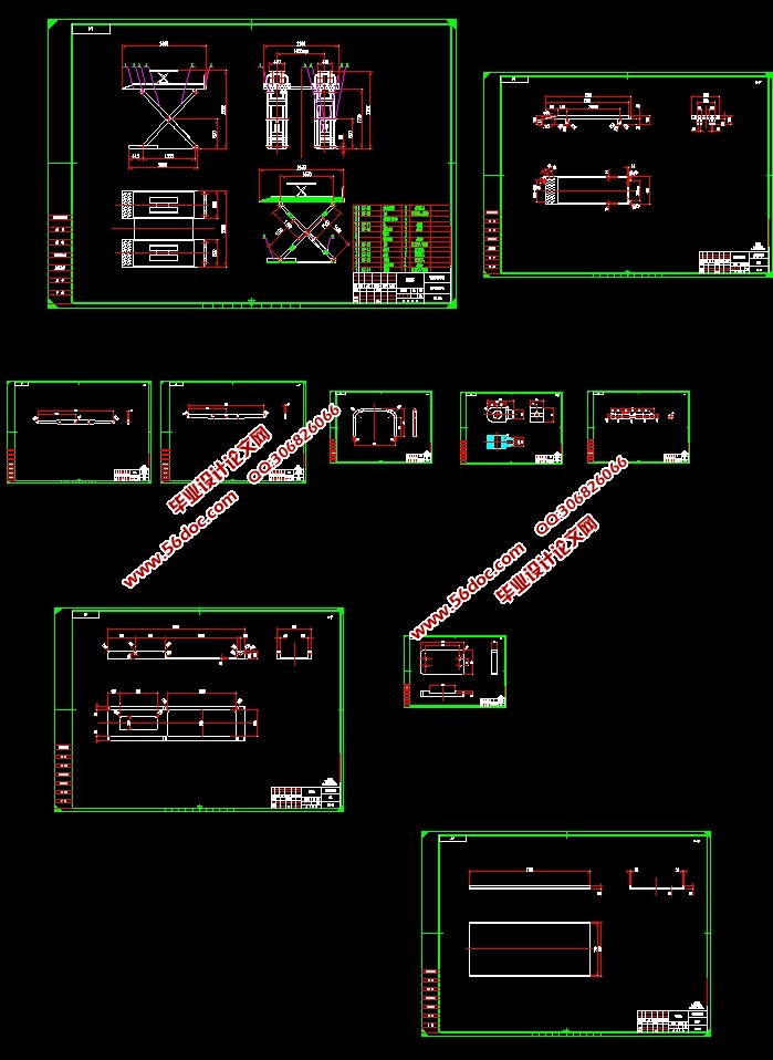
汽车检修升降台架的设计(含CAD零件装配图,SolidWorks三维造型)(论文说明书9600字,CAD图纸10张,SolidWorks三维图)
The design of vehicle inspection and lifting platform
摘要
随着科技和社会的发展和进步,各种各样的车辆将会陆续出现在公路上面,与此同时,随着时间的推移,汽车之间发生的交通事故也越来越频繁,如果不对汽车进行检修,最基本的就是严重影响了汽车的外观,严重的导致汽车不能继续使用,在以前,我国对这种现状的重视程度还是不够,即在交通工具上有自带的检修工具,但这对于难度大点的检修工作就带来困难,例如车底盘,如果发生故障,根本就不能够检修,而且这种现状存在着许多不和谐因素,更使群体分化加剧,社会人文关怀程度的下降。而如果能够经常对汽车进行检修,将会大大提高汽车的使用年限和外观美,给人们一个安全、放心的驾驶环境。
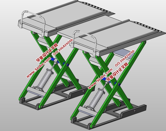
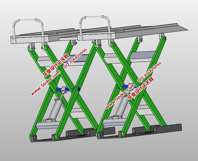
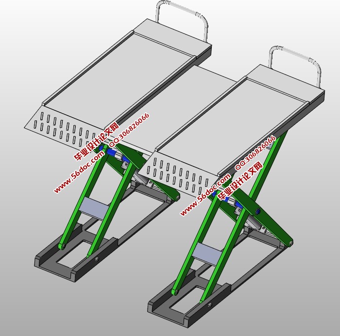
本次设计是关于汽车检修升降台架的设计,通过对传统的汽车检修升降台架结构进行了改进和优化,对它的机械结构和液压系统进行设计,使得此种类型的汽车检修升降台架的使用范围更广泛,更加灵活,并且对今后的选型设计工作有一定的参考价值。
关键词:机械;液压;汽车检修升降台架;参考
Abstract
For a lot of special places, like the risk is very big, or we are difficult to reach, such as disarm bombs, unknown corresponding domains such as detection, probing deep of more dangerous situation usually need to implement the robot.It’s a main part of robot for micro pedipulator, walking robots and more than six feet, compared to the Eight Legged Robot, because of strong bearing capacity, good stability, which the meritss is simple construction, So, a large number of researchers around the world, start .This paper mainly to the four bar mechanism as the main execution elements to design of micro walking the whole scheme of the four bar mechanism.
Its principle is diagonal synchronization, leg activity by the structure of the crank rocker, front leg movements around the same, it detailed performance curve characteristics of the connecting rod,when the curve trajectory diagonal straight line segment, the robot is stationary, the motion trajectory when the diagonal curve is slanting line do the walking.
Keywords:Manufacturing ,Location, Clamping, Process
2.2.3 汽车检修升降台架主要尺寸的确定
1、汽车检修升降台架高度
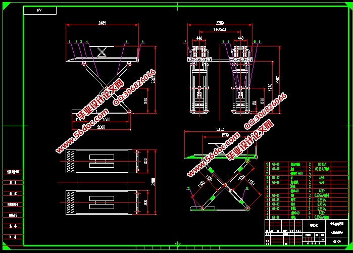
汽车检修升降台架最小高度为:Hm=1.7m
汽车检修升降台架最大高度为:Hn=2.3m
2、汽车检修升降台架伸缩比
汽车检修升降台架的伸缩比指最大与最小汽车检修升降台架高度之比值为: 代入数据得m=2。
2.2.4 汽车检修升降台架间距
所谓汽车检修升降台架间距,就是相邻两汽车检修升降台架中心线间的距离。按下式计算:bc=Bm+n∙C3;
式中:
bc—汽车检修升降台架间距(汽车检修升降台架中心距);
Bm—每架汽车检修升降台架升降台总长度;
C3—相邻汽车检修升降台架(或框架)升降台之间的间隙;
n—每架所包含的组架的组数或框架数,整体自移式汽车检修升降台架。
汽车检修升降台架间距bc要根据汽车检修升降台架型式来确定,本次设计取汽车检修升降台架的中心距为1.4m。

目 录
摘要 I
Abstract II
1引言 1
1.1课题的来源与研究的目的和意义 1
1.2本课题研究的内容 3
1.3汽车检修升降台架的发展现状 5
1.4液压传动的基础知识 5
2汽车检修升降台架总体结构的设计 7
2.1汽车检修升降台架的总体方案图 9
2.2汽车检修升降台架的总体设计 12
2.2.1确定检修升降台架参数的原则 12
2.2.2确定检修升降台架结构参数的内容 12
2.2.3检修升降台架主要参数的确定 13
2.2.4检修升降台架间距 15
2.3 四连杆机构的设计 16
2.3.1四连杆机构的作用 16
2.3.2四连杆机构的几何作图法 17
2.4液压缸的选型计算 17
2.4.1缸体壁厚的计算 18
2.4.2缸底厚度的计算 20
2.4.3缸筒发生完全塑性变形的压力计算3.2.4缸筒径向变形计算 21
2.4.4活塞杆强度的计算 22
2.4.5 管路的设计 22
3负载图和速度图 22
4各主要零部件强度的校核 23
4.1升降台的强度校核 24
5 汽车检修升降台架的控制原理 26
结论 27
致谢 28
参考文献 29
|


