液压阀腔零件机械加工工艺规程及工装设计(含CAD零件图夹具图)(论文说明书10200字,CAD图纸5张,工序卡,工艺卡)
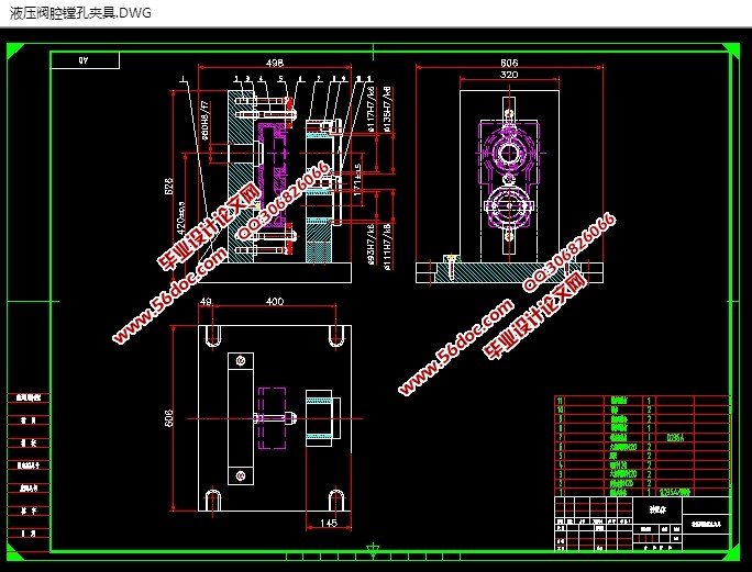
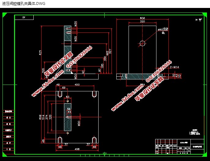
摘要:本毕业论文主要讲的是液压阀腔零件机械加工工艺规程及工装设计,设计镗孔夹具的设计过程。首先进行零件的分析,利用CAD绘出零件图,分析结构特点,接着确定零件主要加工要求然后进行工艺规程及夹具设计,确定毛坯利用CAD画毛坯图,确定定位基准,制定工艺路线,计算切削余量,最后再做镗φ100和φ76两孔的夹具设计。在设计的时候应该选择定位基准和夹紧方案,选用合适的定位元件和夹紧装置,接着进行定位误差的分析、计算切削力及夹紧力,判断夹具设计的合理性。
本文的研究重点在于通过对液压阀腔的工艺性和力学性能分析,对加工工艺进行合理分析,选择确定合理的毛坯、加工方式、设计高效、省力的夹具以及设计出简单、实用的数控加工程序,通过实践验证,最终加工出合格的液压阀腔零件。
关键词:液压阀腔,加工余量,工艺,夹具
Abstract:Enable producing the target in process of production raw materials, the blank , state of quality and quantity on part become always take place direct course of change ask craft course, if the blank is made, machining, heat treatment , assemble etc. and call it the craft course. In the course of making the craft , is it confirm every erector location and worker step that process need this of process to want, the locomotive of processing , this process , and the entering the giving amount of the lathe, cut depth , the rotational speed of the main shaft and speed of cutting, the jig of this process, the cutter and measuring tool, a one hundred sheets of number of times still leaves and a one hundred sheets of length leaves, calculate basic time of this process , auxiliary time and service time of place of working finally.
At present, part of the processing of domestic have begun to close to the machine tool, but also need to clamp the workpiece, that is to say, although the technology has been greatly improved but his nature has not changed much, on the flip side, because of his skill and precision is high, so a high quality tool holder of machine tools is an absolute necessity. As everyone knows, because our technology in the unceasing development, technical requirements for processing of the knife is also more and more high, before an ordinary lathe is clamped four tool, and now there is a large number of will not meet the work requirements, therefore, tool holder part can clamp the tool also needs our staff to develop.
Keywords:fixture multi-function;Die forging links;Group technology;clipping tight
2 零件的分析
2.1 夹具的发展史
题目所给的零件是液压阀腔,而液压阀腔一般是板状物,上面钻或铣有直孔或者是凹台,其是液压阀的腔体,而本课题的任务就是“液压阀腔零件机械加工工艺规程及工装设计”。
2.2 零件的工艺分析
(1)以主视图为主要加工表面的加工面。
这一组加工表面包括:
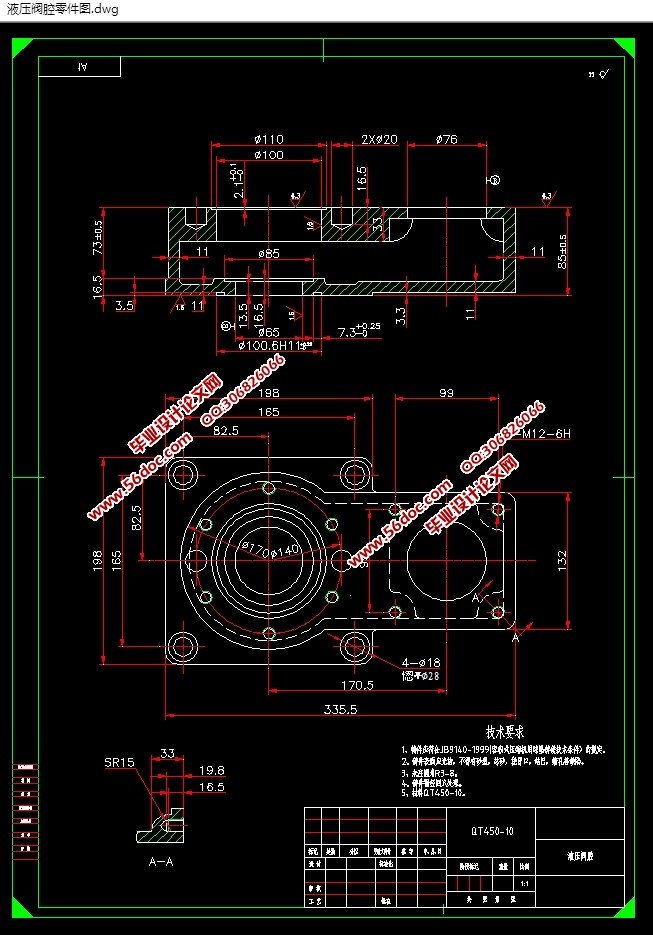
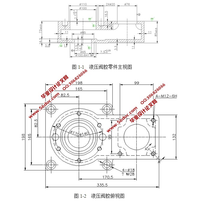
液压阀腔上下表面的铣削加工,上表面表面粗糙度为 ,下表面的表面加工精度要高,粗糙度为 。下表面深3.3凹台的铣削加工。其表面粗糙度为 。∮100,∮176,∮65孔的镗削加工,∮110,∮85凹台的铣削加工,其表面粗糙度为 。
(2)以俯视图为主要加工表面的加工面。
这一组加工表面包括:
4-M12-6H螺纹孔的钻、攻加工,6-M12-6H螺纹孔的钻、攻加工,4-∮18直孔的钻削加工,∮28沉孔的愡削加工,2-∮20盲孔的钻削加工。
目 录
摘 要 I
Abstract II
第一章 绪论 1
第二章 零件的分析 5
2.1 零件的作用 5
2.2 零件的工艺分析 5
第三章 确定毛坯,绘制毛坯图、零件图 8
3.1确定毛坯的制造形式及材料 8
3.2机械加工余量、工序尺寸及毛坯尺寸的确定 8
第四章 工艺规程设计 10
4.1定位基准的选择 10
4.2制定工艺路线 10
4.3选择加工设备及刀、夹、量具 14
4.4 确定切削用量及基本工时 16
4.4.1粗铣上下平面,见光即可 17
4.4.2精铣上下平面,保证厚度尺寸 到位 20
4.4.3粗、精铣厚度3.3缺口到位 20
4.4.4铣主视图中 深2.1凹台 19
4.4.5粗铣、精铣 深3.5凹台 19
4.4.6粗镗、精镗 、 孔 20
4.4.7粗镗、精镗 孔。 20
4.4.8铣主视图中 深3凹台 20
4.4.9钻俯视图中4- 通孔,愡平4- 孔 20
4.4.10钻攻俯视图中6-M12-6H螺纹孔 20
4.4.11钻攻俯视图中4-M12-6H深16.5螺纹孔 20
第五章 镗孔夹具的设计 26
5.1问题的提出 32
5.2夹具的设计 32
结 论 32
致 谢 32
参考文献 33
|


