齿轮箱壳体双面铣专用机床及夹具设计(含CAD零件图装配图)(任务书,开题报告,外文翻译,论文说明书10000字,CAD图纸7张)
摘 要
在本文中,齿轮箱壳体的加工提出“一次装夹,多处理,产品设计达到精度要求,”按照这个思路完成组合双面铣专用机床设计。首先,设计这款组合机床的主要原因,是因为需要可以快速高效的大批量的加工齿轮箱的两个端面。组合机床高效生产的特点恰好符合这些要求。在本文中有详细的计算和设计参数。
首先从要被加工的零件出发,通过分析零件,制定出机床设计的大概方案,其中主要集中点在工艺方案的选定。进而进行总体方案的确定,设计机床的主要参数,接着设计主轴。最后,还需要为机床设计专用夹具。
关键词:齿轮箱,机床,工艺方案,主轴,夹具设计
Gearbox Housing Sided Milling Specific Machine and Fixture Design
Abstract
In this article, the processing of the gearbox housing proposed "a fixture, multi-processing, product design to achieve the accuracy requirements," according to this idea to complete the combination sided milling specific machine design. First, the main reason for this combination of machine design, because the two end faces need fast and efficient processing of large quantities of the gearbox. Efficient production combined machine features exactly meets these requirements. Detailed calculation and design parameters herein.
First, from the part to be machined is obtained by analyzing the development of the overall machine design of the bill, which focuses on the selected process plan, and then the overall layout, to determine the main parameters of the machine, then the spindle design. Finally, we need to machine design special fixtures.
Key words: gear box, machine tool, process scheme, principal axis ,fixture design
目 录
摘 要 III
Abstract IV
1 绪论 1
1.1组合机床的概论 1
1.2 组合机床的发展现状与趋势 1
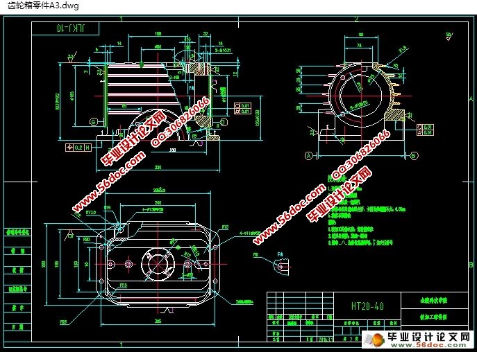
2 齿轮箱壳体加工工艺过程及分析 2
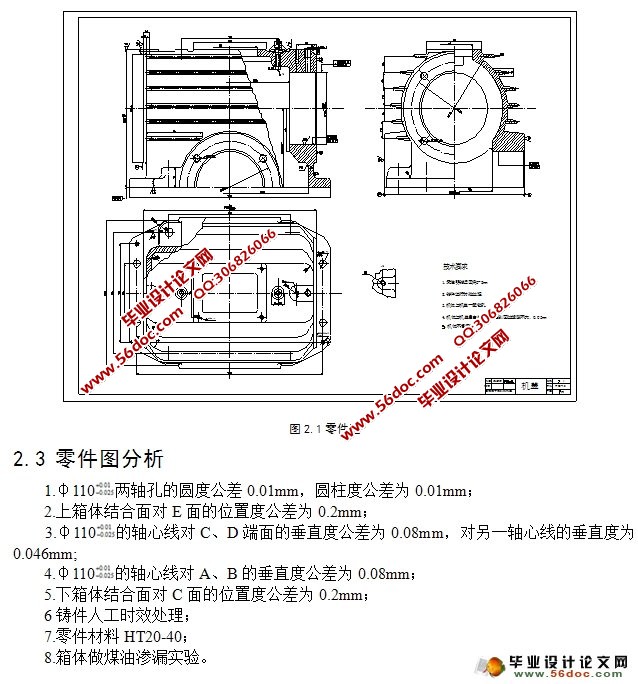
2.1 齿轮箱壳体的主要技术要求 2
2.2 齿轮箱壳体的机械加工工艺过程 2
2.3 零件图分析 3
2.4 齿轮箱壳体加工的工艺路线 3
2.5 加工顺序的安排 3
3 组合机床总体设计 7
3.1 组合机床方案的制定 7
3.1.1 制定工艺方案的基本原则 7
3.1.2 绘制被加工零件工序图的规定及注意事项 7
3.1.3工序图 8
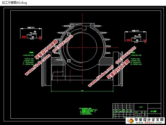
3.2加工示意图 8
3.2.1 加工示意图的内容和作用 8
3.2.2 绘制加工示意图的注意事项 9
3.2.3 选择刀具,导向及有关计算 9
3.2.4 加工示意图 10
3.3机床联系尺寸图 10
3.3.1 机床联系总图的内容 10
3.3.2 绘制机床联系总图注意事项 11
3.3.3 机床的分组 11
3.3.4 机床联系尺寸总图 11
3.3.5 机床生产率计算卡 12
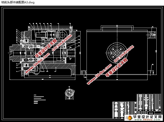
4 铣削头部件设计 13
4.1 机床主要技术参数的确定 13
4.1.1 确定工件余量 13
4.1.2 选择切削用量 13
4.1.3 运动参数 13
4.1.4动力参数—主运动驱动电动机功率的确定 14
4.2 进给驱动电动机功率的确定 15
4.3 主轴组件的计算 15
4.3.1 主轴直径的选择 16
4.3.2 主轴前后支承轴承的选择 16
4.3.3 主轴内孔直径 17
4.3.4 主轴前端悬伸量 18
4.3.5 主轴支承跨距 18
4.4 主轴结构图 18
4.5 主轴组件的验算 19
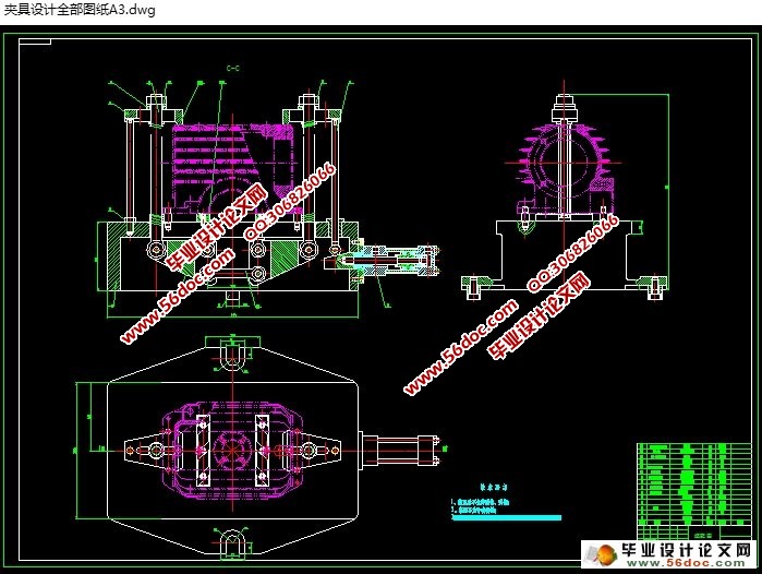
5铣侧面夹具设计 20
5.1设计要求 20
5.2夹具设计 20
5.2.1 定位基准的选择 20
5.2.2 切削力及夹紧力的计算 20
5.3 误差分析与计算 22
5.4夹具设计及操作的简要说明 22
总结 23
参考文献 24
致谢 25
|
