摘要:为保证ZH1105W柴油机齿轮室盖孔加工及保证相应的位置精度,设计一台钻镗组合机床。在完成“三图一卡”的基础上,完成夹具设计。
根据ZH1105W柴油机齿轮室盖的工序图分析其精度、表面粗糙度、技术要求、加工部位尺寸、形状结构、材料硬度、工件刚性及零件的批量的大小不同,确定被加工零件工艺方法和工艺过程,确定该组合机床的总体设计方案;考虑该零件表面结构的不规则性但有较高精度的孔需要加工,定位基准选择“一面双孔”是最佳的方法。选择通用导套,保证零件上孔的位置精度。选用液压滑台来保证所需要的进给力。动力箱和机床底座都是经过严格的计算后再选择合适的标准件,减少机床设计周期和成本;在夹具设计方面采用“一面两销”的定位方案保证被加工孔的准确定位和尺寸精度。考虑到需要的夹紧力比较大和手动夹紧的局限性,选用了液压自动夹紧的方案,提供稳定的夹紧力,减少工人的操作时间并且满足中批量生产的要求。
此次设计的组合机床,结构简单、维护方便,大量使用了通用部件来降低制造成本,达到了设计的要求。
关键词:齿轮室盖;组合机床; 总体设计; 夹具;
Overall and jig design of drilling and boring modular machine for the diesel engine gear cap
Abstract: In order to guarantee the hole processing and the corresponding position precision of the ZH1105W diesel engine gear cap, to drilling and the boring modular machine is designed. It mainly completes the jig design bases on “three charts and a card”.
According to the working procedure chart of the ZH1105W diesel engine’s gear cap analysis work piece’s precision, the surface roughness, the specification, the processing spot size, the shape structure, material degree of hardness, the work piece rigidity and the different of the components batch size to definite technique and technological process, determine aggregate machine-tool’s overall plan. Consider to the irregularity components but have high accuracy holes to be processing. So, “two holes at a face” is the best localization plan. Choiceing the general leads the wrap to Guarantee the hole of the components’ position precision. In order to guarantee the needs of the entering strength, we select hydraulic pressure sliding table. The power box and the engine bed are the standard parts base on our strict computation, so that we can greatly reduce the engine bed design cycle and the cost; In the jig aspect, we use the "two sells at the same face" for the localization plan. Only this way, we can guarantee the hole the accurate localization and the size precision. Considered to the strength of the manual clamps quite be small, selecting the hydraulic pressure clamps is the best way. It could provide stably clamps the strength, reduced worker's operating time and to satisfy the volume production request greatly.
Besides satisfying the processing request, the structure is simple, the maintenance is convenient. The general parts are massively used to reduce the production cost and meet the design requirements.
Key words: The gear cap; Modular machine-tool; Overall design; Jig;
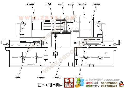
本次设计的ZH1105W柴油机齿轮室盖三面钻镗组合机床采用单工位的工作方式,在加工生产线上同时完成了三道工序,大大提高了生产效率,降低了劳动强度,从而降低了零件的加工成本。同时采用“一面两销”的定位方式和液压夹紧方法,保证了加工精度,提高了加工效率。并且在设计之中,尽量选用通用件,进一步减少了制造成本,从而增加了经济效益。
本组合机床设计合理,符合实际应用,满足加工要求,且较大部分采用通用件和标准件,制造成本合理,机床操作简单,设备调整、维修方便。本设计也有不足之处如:结构不够紧凑、机床占地面积大等。
组合机床工艺方案的制定
制订工艺方案是设计组合机床最重要的步骤.为了使工艺方案制订得合理、先进,必须认真分析被加工零件图纸开始,深入现场全面了解被加工零件的结构特点、加工部位、尺寸精度、表面粗糙度和技术要求及生产率要求等,总结设计、制造、使用单位和操作者丰富的实践经验,理论与生产实际紧密结合,从而确定零件在组合机床上完成的工艺内容及方法。
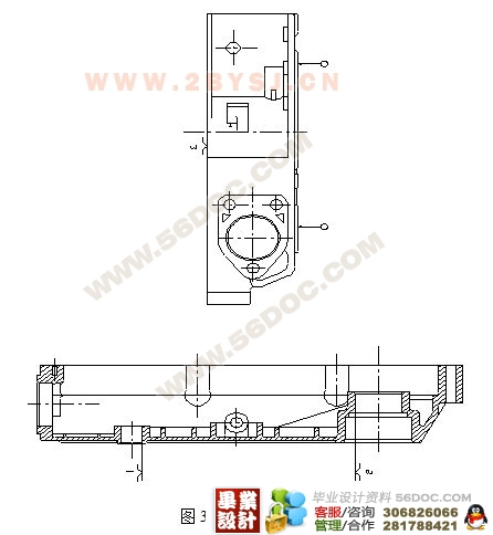
根据所提供ZH1105W柴油机齿轮室盖的工序图,分析被加工零件的精度,表面粗糙度,技术要求,加工部位尺寸,形状结构;特点材料硬度。工件刚性及零件的批量的大小不同,设计的组合机床必须采用不同的工艺方法和工艺过程。
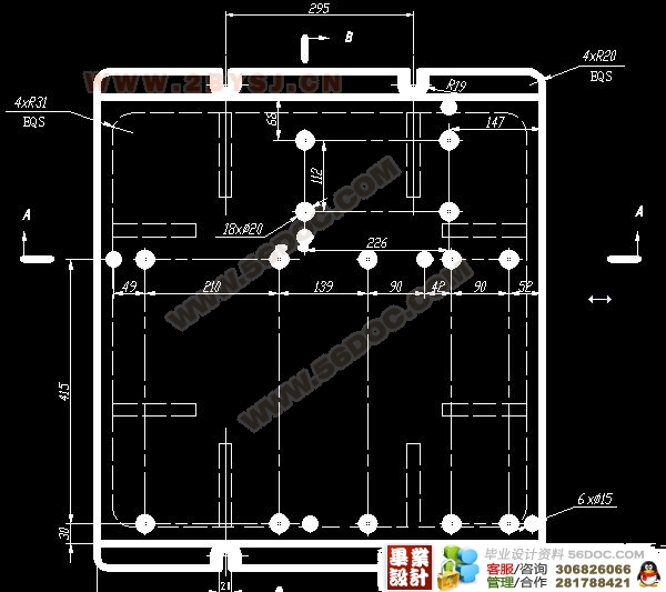
被加工零件需要在组合机床上完成的加工工序及应保证的加工精度是制定机床方案的主要依据。
此次设计的被加工零件是柴油机齿轮室盖,其主要的加工工序如下:
a. 钻6-M6-6H孔至¢5, 左侧面;
b. 钻6-¢9孔(深38), 右侧面;
c. 钻3-¢9孔(深78), 右侧面;
d. 镗¢45H8孔至¢43.5, 后侧面;
e. 倒孔口角至¢46.6, 后侧面.
被加工零件材料为HT250,结构为非对称箱体,是三面加工。
根据各种要求,分析其优缺点,确定设计的组合机床采用机械卧式组合机床。根据所需加工孔的尺寸精度和表面粗糙度,可以确定这些孔的加工采用麻花钻,即可满足要,为了保证孔的加工刀具的直径与加工部位尺寸相适应,需要专门设计制造。
目 录
1前言………………………………………………………………………………………1
2组合机床总体设计………………………………………………………………………2
2.1组合机床工艺方案的制定…………………………………………………………….2
2.2定位基准的选择……………………………………………………………………….2
2.3确定机床布置型式及结构方案……………………………………………………….3
2.4本工序的加工方法…………………………………………………………………….3
2.4.1刀具的选择…………………………………………………………………………..3
2.4.2右侧面钻9-¢9……………………………………………………………………..3
2.4.3左侧面钻6-¢5………………………………………………………………………7
2.4.4后侧镗¢45H8………………………………………………………………………11
2.4.5机床生产率计算卡………………………………………………………………….13
3夹具设计…………………………………………………………………………………15
3.1定位原理及其实现……………………………………………………………………15
3.2误差分析………………………………………………………………………………15
3.2.1影响加工精度的因素……………………………………………………………….16
3.2.2保证加工精度……………………………………………………………………….17
3.3夹紧方式………………………………………………………………………………18
3.4夹紧力数值的计算……………………………………………………………………18
(毕业设计)
3.4.1确定夹紧力时应考虑的计算系数…………………………………………………18
3.4.2确定夹紧力………………………………………………………………………….19
3.5夹紧点数目及位置…………………………………………………………………..19
3.5.1夹紧点的数目………………………………………………………………………19
3.5.2夹紧点的位置………………………………………………………………………20
3.6夹具的主要零件结构设计…………………………………………………………..21
3.6.1钻模类型选择………………………………………………………………………21
3.6.2钻套的结构设计……………………………………………………………………21
3.6.3钻模板的结构设计…………………………………………………………………21
4零部件的设计绘制…………………………………………………………………….23
4.1绘制尺寸联系图…………………………………………………………………….23
4.2绘制加工零件工序图……………………………………………………………….23
4.3绘制加工示意……………………………………………………………………….23
4.4绘制夹具装配图及其零件图……………………………………………………….23
5结论………………………………………………………………………………….24
参考文献………………………………………………………………………………25
致谢……………………………………………………………………………………26
附录……………………………………………………………………………………27
附 录
序号 图 名 图 号 图 幅
1 被加工零件工序图 ZH1105W-01-01 A0
2 加工示意图 ZH1105W-01-02 A0
3 机床总体尺寸联系图 ZH1105W-01-03 A0
4 夹具装配图 ZH1105W-02-01 A0
5 夹具体 ZH1105W-02-04 A1
6 右侧钻模板 ZH1105W-02-10 A2
7 左侧支架 ZH1105W-02-02 A2
8 定位销 1 ZH1105W-02-09 A3
9 定位销 2 ZH1105W-02-12 A3
10 钻模板 ZH1105W-02-06 A3
11 后侧镗支架 ZH1105W-02-03 A3
12 压头 ZH1105W-02-07 A4
13 定位块 ZH1105W-02-11 A4
|
