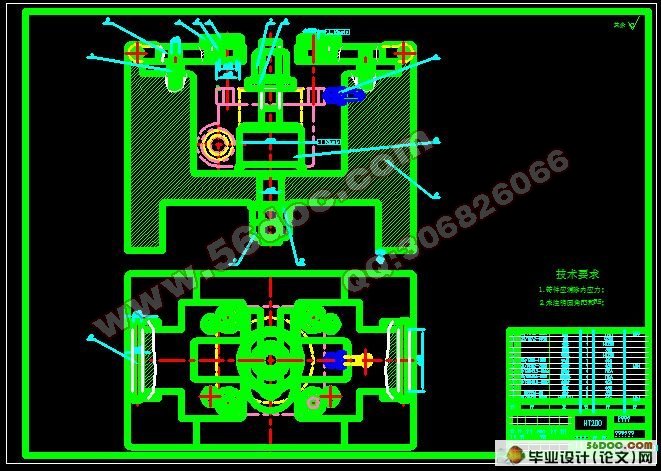
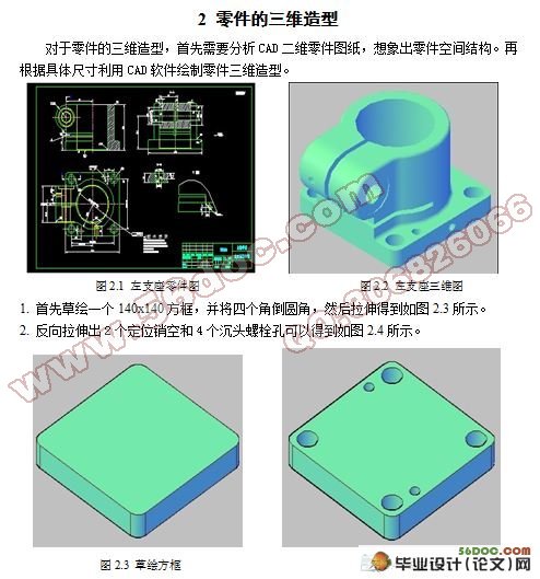
基于左支座零件的工艺及工装设计(含任务书,开题报告,外文翻译,毕业论文19000字,进度检查表,CAD图纸3张)
摘 要
此次设计任务是对做支座零件的工艺及工装设计,在生产过程中,使生产对象(原材料,毛坯,零件或总成等)的质和量的状态发生直接变化的过程叫工艺过程,如毛坯制造,机械加工,热处理,装配等都称之为工艺过程。在制定工艺过程中,要确定各工序的安装工位和该工序需要的工步,加工该工序的机车及机床的进给量,切削深度,主轴转速和切削速度,该工序的夹具,刀具及量具,还有走刀次数和走刀长度,最后计算该工序的基本时间,辅助时间和工作的服务时间。选择其关键工序之一进行专用夹具及加工用组合机床设计,并完成必要的设计计算。定位采用一面一心轴的定位方式,采用这种方式完全能够满足精度要求。而且简易方便,制造成本低,通用性好。由于支座体的生产量比较大,为了保证产品质量,提高加工效率,需要对其加工工艺进行优化设计,并在关键工序使用组合机床或专用机床进行加工。
关键词:工艺规程;定位误差;夹紧;加工余量;夹紧力
Abstract
This design task is to do the support parts of the process and tooling design, Enable producing the target in process of production (raw materials, the blank, state of quality and quantity on part become always ) take place direck course of change ask craft course, it the blank is made, machining, heat treatment, assemble etc. and call it the craft course. In the course of making the craft , is it confirm every erector location and worker step that process need this of process to want, the locomotive of processing, this process, and entering the giving amount of the lathe, cut depth ,the rotational speed of the main shaft and speed of cutting , the jig of this process , the cutter and measuring tool , a one hundred sheets of number of time still leaves and a one hundred sheets of length leaves , calculate basic time of this process , auxiliary time and service time of place of working finally. chooses one of its critical processes to carry on the unit clamp and the processing with the aggregate machine-tool design, and completes the essential design calculation. The localization uses a spindle's locate mode, to select this method definitely to be able to satisfy the accuracy requirement. Moreover simple convenient, the production cost is low, the versatility is good. Because the support body's productivity is quite big, for the quality assurance, raises the processing efficiency, needs to carry on the optimization design to its processing craft, and carries on the processing in the critical process use aggregate machine-tool or the special purpose machine.
Key words :Technical instruction; position error; clump; the surplus of processing; clamp strength
研究内容
要求能够应用三维软件对零件进行三维造型,并通过实际调研和采集相应的设计数据、分析金属切削加工过程中的机床、刀具的选择、切削用量的确定、工序尺寸确定、工件装夹等方面的相关数据,结合机械理论设计与方法、金属切削机床、典型零件工艺工装设计等知识、完成典型零件的机械加工工艺文件编制及实施等相关内容。
拟采取的研究方法、技术路线、实验方案及可行性分析
(1)研究方法
借阅相关书籍杂志,利用图书馆及网络资源查阅资料。
(2)技术路线
绘制零件三维造型,分析加工零件的工艺性,根据零件生产纲领决定生产类型,制定零件加工工艺规程及工艺路线,确定夹具设计方案。
(3)实验方案
对金属切削加工、金属切削机床、机械制造装备、机械设计与理论等相关知识充分掌握后,对普通机床的运动和夹紧装置进行数学建模。
(4)可行性分析
通过模拟实验分析建立普通机床的驱动、夹紧装置的实体模型,设计适合于该零件实际生产所需要的专用夹具,进行现场实验,来达到产品的最优化设计。
.1.1 零件的作用
题目所给的零件是机床上的一左支座,它用螺钉通过4×Ø13mm孔连接于机架上,4×Ø10mm是定位销孔,底板4×Ø20mm大孔是固定支座的沉头螺栓孔,该零件纵横两方向上5mm的槽使80mm耳孔部分有一定的弹性,利用一端带M20螺纹(穿过于Ø21mm孔)一端于Ø25H7配合的杆件通过旋紧,便装在Ø80H9孔内的心轴定位并夹牢,松开螺栓后轴杆可转动或者滑动, 也可利用夹紧程度不同来调节孔与轴的间隙。


目 录
摘 要 III
ABSTRACT IV
目 录 V
1 绪论 1
1.1 本课题的研究内容和意义 1
1.2 国内外的发展概况 1
1.3 本课题应达到的要求 2
2 零件的三维造型 3
3 车床左支座零件的分析及毛坯的确定 6
3.1 车床左支座的作用和工艺分析 6
3.1.1 零件的作用 6
3.1.2 零件的工艺分析 6
3.2 零件毛坯的确定 7
3.2.1 毛坯材料的制造形式及热处理 7
3.2.2 毛坯结构的确定 7
4 左支座的加工工艺设计 9
4.1 基准的选择 9
4.2工艺设计过程中应考虑的主要问题 10
4.2.1 加工方法选择的原则 10
4.2.2 加工阶段的划分 10
4.2.3 加工顺序的安排 10
4.2.4 工序的合理组合 11
4.3 左支承座的工艺路线分析与制定 12
4.3.1 工序顺序的安排的原则 12
4.3.2 工艺路线分析及制定 12
4.4 机械加工余量 14
4.4.1 影响加工余量的因素 14
4.4.2 机械加工余量、工序尺寸以及毛坯余量的确定 15
4.5 确定切削用量及基本工时 17
4.5.1 工序一 粗铣Ø80H9 (+00.087)mm孔大端端面 17
4.5.2 工序二 粗镗Ø80H9(+00.087)mm内孔 20
4.5.3 工序三 精铣Ø80H9(+00.087)mm大端端面 20
4.5.4 工序四 精镗Ø80H9(+00.087)mm内孔 22
4.5.5 工序五 钻削4-Ø13mm的通孔,锪沉头螺栓孔4-Ø20mm 22
4.5.6 工序六 钻削Ø21mm的通孔,扩、铰孔Ø25H7(+00.021)mm,锪削Ø38mm的沉头螺栓孔 24
4.5.7 工序七 锪削沉头螺栓孔Ø43mm 26
4.5.8 工序八 钻削M8-7H的螺纹底孔 26
4.5.9 工序九 铣削尺寸为5mm的纵槽 27
4.5.10 工序十 钻削M10-7H的螺纹底孔 27
4.5.11 工序十一 铣削尺寸为5mm的横槽 28
4.5.12 工序十二 攻螺纹M8-7H和M10-7H 28
5 专用夹具设计 30
5.1 钻夹具设计 30
5.1.1 定位基准的选择 30
5.1.2 切削力及夹紧力的计算 31
5.1.3 误差分析与计算 31
5.1.4 夹具设计及操作的简要说明 31
5.2 铣夹具设计 31
5.2.1 定位基准的选择 31
5.2.2 设计步骤 31
6结论与展望 34
6.1 结论 34
6.2不足之处及未来展望 34
致 谢 35
参考文献 36
附 录 37
|


