小型折叠臂式高空作业车的设计(含CAD图)(开题报告,外文翻译,论文设计说明书18000字,CAD图纸4张)
摘 要
本设计主要以小型折臂式高空作业车上、下臂结构为研究对象,对上、下臂进行结构和该车上`的设计。主要分两部分进行阐述,第一部分:根据高空作业车的最大高度10米,在满足作业高度的前提下,进行高空作业臂的结构设计:首先根据作业载荷使用要求选择作业臂材料类型;其次根据最大作业高度确定上、下长度;在经过受力分析利用强度来确定臂的截面尺寸,进而校核强度、刚度、稳定性,查看作业臂的尺寸是否符合要求。对施加均布载荷和约束,进行结构的强度和刚度的分析,确定危险截面或危险点的应力分布及变形,最后画出作业臂的总装图。第二部分:液压控制部分主要是指控制上下臂变幅运动的液压缸。文中详细记录了高空作业机构上下臂液压缸的设计过程,在确定液压系统元件参数的基础上,完成了液压传动系统的设计计算。
关键词:折叠臂式高空作业车,折叠臂式液压系统设计,专用汽车,设计
ABSTRACT
In this paper , to” high-altitude vehicles”,under the arm to study de structure of the upper and the lower arm to the vehicles structure and the design of the hydraulic system,mainly conducted in two parts on,high-aititude vehicles under one of the largest 10 meters high degree of operating,to meet the high degree of operating under the premise of a high-aititude operations arm of the structural design ,first,the use of operating arm asked to choose the type of material and secondly in accordance with the largest Operating highly determined ,under the arm length ;another use of force analysis to determine the strength of the arm section size and location of the fuel tank of the hinged ;further strength ,stiffness,the stability of checking to see whether the size of the operating arm to meet the requirements .to impose uniform loading and constraints ,structural strength and stiffness analysis, risk and danger point cross-section of the stress and deformation ,finally draw operating arm and hand ,arm parts under the plans .and hydraulic control of the mainly refers to control the movement from the top to bottom arm change hydraulic cyclinders .In a detailed record of the agencies operating at high altitude upper arm hydraulic cylinders and hydraulic cylinders under the arm of the design of process .In the determining the parameters of the hydraulic system components ,based on the completion of the hydraulic system desion and calculation.
Key words: Folded-arm high-altitude vehicles Folding arm type hydraulic system design Special Vehicle Design
2.1 总体设计要求
本毕业设计要求设计一辆高为10米高空作业车,其具体要求如下:
1、设计任务:10米高空作业车的改装设计。
2、机器用途:通用型,适用于建筑、安装、管道铺设等高空作业。
3、工作环境:风力六级以下,温度-20~30℃,无腐蚀性极易爆易燃性气体。
表2.1 作业部分主要技术参数
最大作业高度 10-10.5m
回转角度 360°
额定平台载荷 200kg
操作方式 下操作、上操作可以任意选择
支腿形式/数量 H型/8
最大作业幅度 2.3-2.75m
2.2 动作要求
1、回转台左右均可以全周回转360°。
2、起升和旋转可以同时进行且互不干涉。
3、垂直支腿在高空作业车非工作状态下可以自由缩放。
4、水平支腿在高空作业车非工作状态下可以自由的扩放支腿的支承范围。
5、制动器可以随时制动回转马达的转动。
2.3 技术性能要求
动作平稳、安全可靠、操作方便、体积小、自重轻。
2.4 总体设计方案
1、本车采用EQ1050NJ20D3汽车底盘改装。
2、本车各机构(不包括作业平台)均采用液压传动。
3、举升机构采用两节折叠臂形式。
4、支腿机构采用8个液压缸的H形支腿。
5、转台的设计。
6、液压系统的设计。


目 录
摘 要 I
Abstract II
第1章 绪 论 1
1.1 概述 1
1.2 高空作业车的发展现状 2
1.2.1 专用车的现状 2
1.2.2 我国高空作业车的现状和发展 2
1.3 高空作业车的组成 5
1.3.1 工作装置 5
1.3.2 金属结构 5
1.3.3 控制系统 5
1.3.4 动力传动装置 5
1.4 本课题所研究的任务 6
1.5 本课题研究的意义 6
第2章 确定设计方案 8
2.1 总体设计要求 8
2.2 动作要求 8
2.3 技术性能要求 8
2.4 总体设计方案 8
2.5 确定执行元件的形式 9
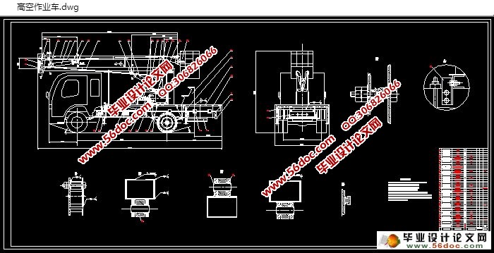
2.6 整体设计结构图 9
2.7 本章小结 9
第3章 底盘的选择 10
3.1 高空作业车底盘的类型 10
3.2 底盘的选择 10
3.3 本章小结 11
第4章 高空作业车臂的设计 12
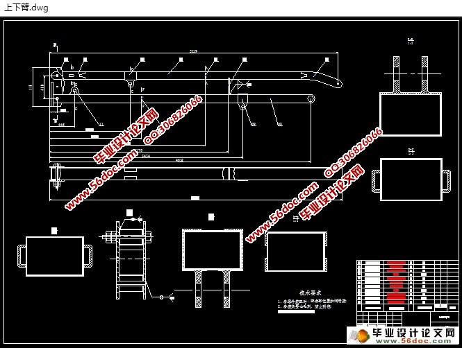
4.1 材料的选择 12
4.2 计算上、下臂的长度 12
4.3 确定液压缸铰点的位置 13
4.3.1 确定上臂液压缸铰点的位置 13
4.3.2 确定下臂液压缸铰点的位置 13
4.4 上臂截面尺寸的确定 13
4.4.1 对上臂进行受力分析 14
4.4.2 计算上臂截面尺寸 15
4.4.3 对上臂进行强度校核 16
4.5 下臂截面尺寸的确定 17
4.5.1 对下臂进行受力分析 17
4.5.2 计算下臂的截面尺寸 19
4.5.3 对下臂进行强度校核 20
4.6 本章小结 21
第5章 高空作业车转台结构的设计 22
5.1 高空作业车转台总体结构设计 22
5.2 转台的受力分析 27
5.2.1 转台的自重 27
5.2.2 转台受到的其余的力 29
5.3 回转支承装置的计算 29
5.3.1 回转支承的计算载荷 29
5.3.2 转盘式回转支承装置的计算 30
5.3.3 按承载能力确定圆柱滚子数目 30
5.4 传动齿轮的计算 31
5.4.1 选择齿轮材料 31
5.4.2 选择齿轮齿数和齿宽系数 31
5.4.3 确定轮齿的许用应力 32
5.4.4 齿面接触强度设计 32
5.4.5 确定模数和齿宽 32
5.4.6 验算齿根的弯曲强度 33
5.4.7 传动齿轮的几何尺寸 33
5.5 本章小结 33
第6章 液压系统的设计 34
6.1 液压缸的设计计算 34
6.1.1 液压缸的最大载荷 34
6.1.2 确定系统工作压力 37
6.1.3 液压缸内径计算 37
6.1.4 液压缸缸筒壁厚和外径计算 37
6.1.5 液压缸最大密封压强得计算和壁厚的校核 38
6.1.6 液压缸活塞杆直径 40
6.1.7 液压缸活塞缸强度校核 40
6.1.8 液压缸活塞杆稳定性校核 41
6.1.9 液压缸的选择 42
6.2 液压马达的选取 42
6.3 液压泵的选择 42
6.4其他辅助元件的选择 43
6.4.1 油箱 43
6.4.2 联轴器 43
6.4.3 各种液压阀 44
6.5 本章小结 44
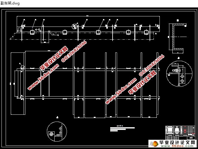
第7章 副车架与其余部分设计与选择 45
7.1 副车架的选择与计算 45
7.1.1 副车架外形设计 45
7.1.2 副车架选材 45
7.1.3 副车架的校核 45
7.2 销和螺栓的校核与计算 48
7.3 钢丝绳的选择与计算 49
7.3.1 钢丝绳的计算与校核 49
7.3.2 钢丝绳接头的压制方法 51
7.4 本章小结 51
结 论 52
参考文献 53
致 谢 54
附 录 55
|


