小型钻铣组合机床传动系统设计(含CAD图)(设计说明书10000字,CAD图纸4张)
摘要
本设计为小型钻铣组合机床传动装置设计。由于此设计需要根据工厂的具体情况(条件),自行设计,制造,能供本厂生产使用的简单的机床,所以本设计是按照工厂生产需要,进行有针对性的设计制造。
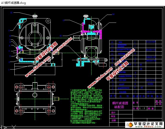
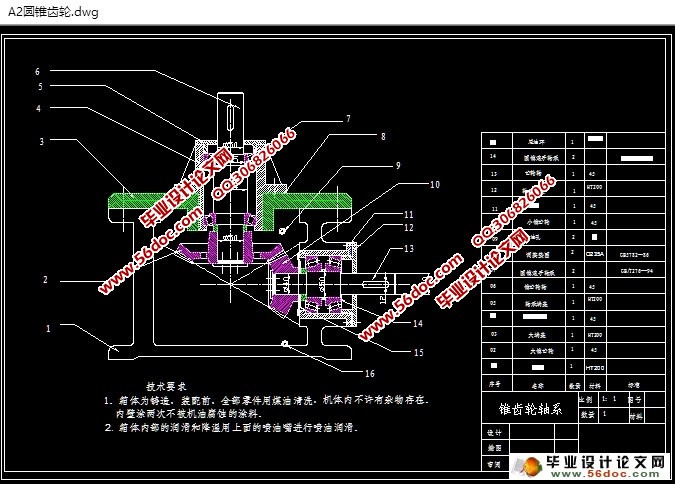
在设计过程中发现,可以利用方案有很多种,但是大部分传动方案由于传动比和结构方面的原因不能使用,只有采用蜗杆—圆锥齿轮减速器。传动比的分配本着机体结构简单、体积小、重量轻的原则来确定,传动零件的设计应尽量选用既能满足要求有是价格低廉的材料。根据小型钻铣床的特点主要使用了两级传动装置,第一级使用了蜗杆减速器,第二级采用了圆锥齿轮减速器,并且这两级减速器分别独立,各为一体。主要是考虑其以后的改装方便和经济性易维护等方面,例如:蜗杆减速器为多用途设计,在本设计中为下置式,若需要上置式则能很快捷方便的进行改装。
本设计的重点和难点部分为多功能蜗杆减速器的设计,它能改成蜗杆上置式工作,也能改成蜗杆下置式进行工作。可利用有限的物力和财力对机床做多功能的改造。
关键词 简易机床; 减速装置; 传动
Abstract
This design for simple horizontal milling machine transmission device design. As a result of this design needs according to the factory special details (condition), independently to design, the manufacture, can supply this factory production use the simple engine bed, therefore this design defers to the plant production need, carries on has the pointed design manufacture.
Discovered in the design process that, may have very many kinds using the plan, but majority of transmissions plan because the velocity ratio and the structure aspect reason cannot use, only then uses the worm bearing adjuster bevel gear reduction gear. The velocity ratio assignment in line with the body structure simple, the volume is small, the weight light principle determined that, the transmission components design should select as far as possible already can answer the purpose has is the price inexpensive material. Has mainly used two levels of transmission devices according to the horizontal milling machine characteristic, the first level has used the worm reducer, the second level has used the bevel gear reduction gear, and these two levels of reduction gears distinction is independent, each is a body. Mainly is considered its later the reequipping convenience and the efficiency will be easy to maintain and so on the aspect, for example: The worm reducer is the multipurpose design, in this design for down-apex, if needs on to set at the type then can very quick Czechoslovakia facilitate carries on the re equipment.


目 录
第一章 传动装置设计 1
1.1 铣床的认识 1
1.2 铣床的传动方式 2
第二章 选择电动机 3
2.1 原始参数 3
2.2 电动机的选择 3
第三章 传动方案的选择 4
3.1 计算总传动比 4
3.2 选择传动形式 4
3.3 传动方案的选择 5
3.3.1 方案一: 5
3.3.2 方案二: 6
3.3.3 方案三: 7
3.3.4 方案四: 8
3.4 方案综合考虑并选用 9
第四章 根据传动方案计算运动参数 10
4.1 传动比的分配 10
4.2 蜗杆,蜗轮传动计算 10
4.2.1 选择材料 10
4.2.2 选择蜗杆蜗轮的齿数 11
4.2.3 确定许用应力 11
4.2.4 按接触强度计算; 11
4.2.5 求蜗轮的圆周速度, 12
4.2.6 校核蜗轮齿面的接触强度 13
4.2.7 蜗轮齿根强度校核 13
4.2.8 计算几何尺寸 13
4.2.9 蜗轮轴的结构设计 14
4.2.10 各轴段轴向长度的确定 15
4.2.11 按许用弯曲应力校核轴 16
4.2.12 蜗杆,蜗轮简图 17
4.3 蜗杆减速器轴承的选用 18
4.3.1 蜗杆轴轴承的选用 18
4.3.2 蜗轮轴轴承的选用 19
4.4 锥齿轮传动设计...... 21
4.4.1 初步设计: 21
4.4.2 几何计算。... 22
4.4.3 接触疲劳强度校核 23
4.4.5 计算接触应力 24
4.4.6 锥齿轮的轴的结构设计 25
4.4.7 按弯扭合成强度校核轴的直径 26
4.4.8 轴承的选用 27
第五章 减速器箱体结构及设计 29
5.1 箱体的结构 29
5.2 箱体的设计 29
5.3 箱体的附件设计 29
5.3.1 观察孔和观察孔盖 29
5.3.2 通气孔 30
5.3.3 油面指示器 30
5.3.4 轴承端盖和密封装置 30
第六章 键的选用 31
6.1 蜗杆减速器键的校核 31
6.2 圆锥齿轮减速器的键的选用 32
第七章 联轴器的选择 33
7.1 高速轴输入端联轴器的选择 33
7.2 减速器之间的联轴器 33
第八章 离合器的选择 34
结论 36
参考文献 37
致谢 38
|


