加工中心侧铣头结构设计(含CAD图,CAXA图)
来源:wenku163.com 资料编号:WK16311435 资料等级:★★★★★ %E8%B5%84%E6%96%99%E7%BC%96%E5%8F%B7%EF%BC%9AWK16311435
资料介绍
加工中心侧铣头结构设计(含CAD图,CAXA图)(论文说明书15700字,CAD图纸3张,CAXA图3张)
Structural Design of the Profile Cutter Head of a Machining Centre
摘要 本设计主要是根据设计要求,依据机械设计和机械制图的基本原理对一台重型数控龙门铣床的侧铣头进行结构设计,该侧铣头能够在X 方向和Z方向两个方向上进行铣削运动。本设计主要分四部分:
第一部分是根据设计要求对侧铣头的结构进行总体方案的设计,主要包括伺服进给运动和主运动方式的确定。
第二部分是利用机械设计基本原理对设计中伺服进给运动和主运动系统的机械部分的设计计算,主要包括进给电动机、主轴电动机、滚珠丝杠副的选则、计算和校核以及对同步带和带轮进行设计。
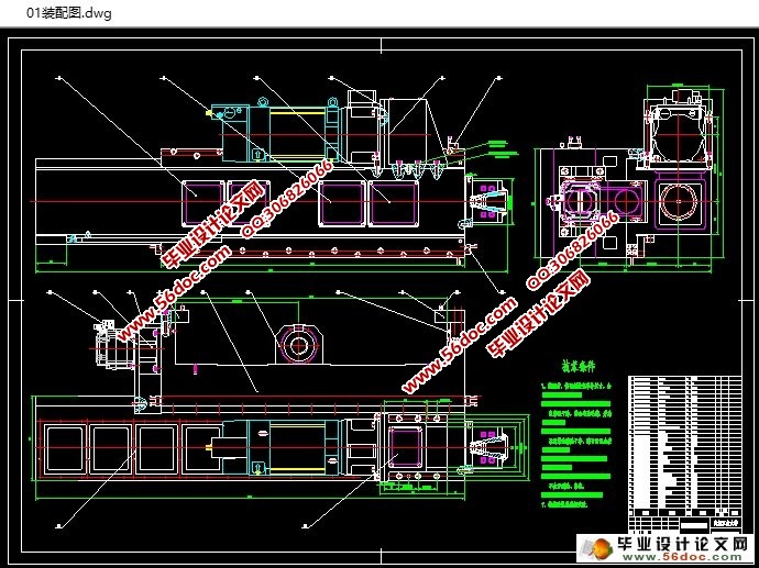
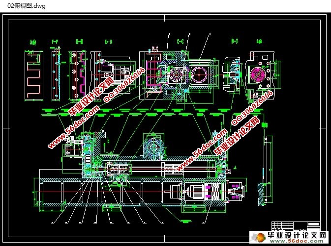
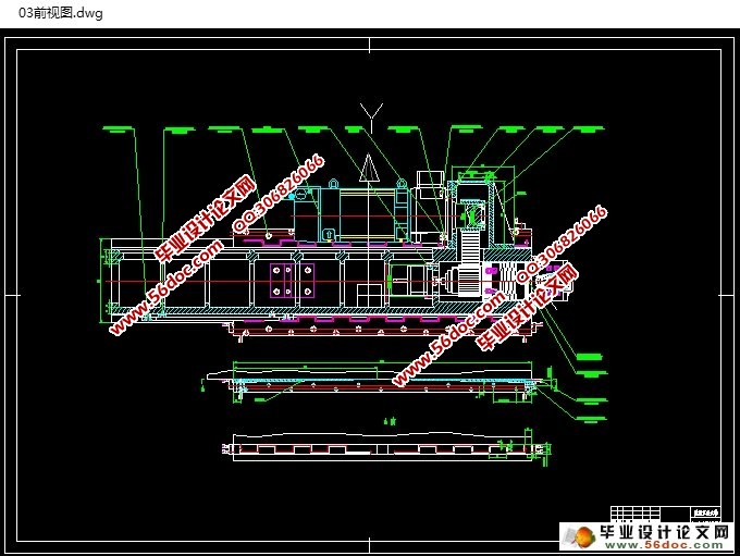
第三部分是根据所选择设计的主要零件,先进行大体结构设计,之后在此基础之上,利用机械制图的基本原理,应用CAXA电子图版对侧铣头的结构进行二维设计,并生成三张二维装配图纸和一张二维零件图纸。
最后一部分是依据所设计的二维图,利用SOLIDWORKS软件对侧铣头结构中零件进行三维建模,并将所有建模零件进行装配,生成三维装配体;在此基础上,利用该软件做一个三维动画,显示装配体内部结构及运动方式。
关键字: 重型数控龙门铣床 侧铣头 结构设计 总体方案设计
二维设计 三维建模 三维动画
Structural Design of the Profile Cutter Head of a Machining Centre
Abstract: The design is mainly to design the profile cutter head structural of a heavy numerically controlled plan miller according as the rationale of mechanism design and theory of machines on the bases of design specification. The design is mainly divided into four parts:
The first part is a content of total project design of the profile cutter head Structure according as design specification, including confirming the manner of servo feed motion and the main motion.
The second part is design of calculations of machine parts of servo feed motion system and the main motion system according as the rationale of mechanism design. Its mainly including chooses the type, the calculation and the verification of the feed electromotor, the principal axis electromotor and the ball screw, and the design of hold-in range and synchronous pulley.
The third part is to design the mainly structure firstly on the bases of main parts choosed and designed in the second part, then to design two dimensional drawings, and create three assembly drawings and one detail drawings using CAXA software according to the rationale of theory of machines.
The finally part is to model the parts of the profile cutter head, and create three dimensional drawings using SOLIDWORKS software according to two dimensional drawings designed in the third part;The following is to create a three-dimensional animation to show the inside structure of the three-dimensional assembly drawing and the motion manner using the software on the bases of the three-dimensional assembly drawing.
Keywords: Heavy numerically controlled plan miller, The profile cutter head, Structural design, total project design, two dimensional design, three dimensional modeling,three-dimensional animation。
设计基本要求
1) 侧铣头的行程为600mm;
2) 定位精度为5ηm ;
3) 与立柱连接部分横跨度为1300mm;
4) 最大进给速度为10 m/min;
5) 两侧铣头中间能通过最大零件宽度为3150mm;
6) 主切削力5000N。
目 录
摘 要………………………………………………………………………………………I
ABSTRACT……………………………………………………………………………П
第一章 绪 论…………………………………………………………………………1
1.1 国内外数控机床的发展状况……………………………………………………1
1.2 数控技术的发展趋势……………………………………………………………2
1.3 设计目的和意义……………………………………………………………………3
第二章 总体方案设计……………………………………………………………5
2.1设计基本要求………………………………………………………………………5
2.2总体设计方案………………………………………………………………………6
第三章 伺服系统机械部分设计计算………………………………………8
3.1滚珠丝杠副的选择计算…………………………………………………………8
3.1.1 已知参数…………………………………………………………………………8
3.1.2 切削力的确定…………………………………………………………………8
3.1.3 滚珠丝扛螺母副的设计、计算………………………………………………8
3.2 进给伺服系统传动计算…………………………………………………………11
3.2.1 电动机选择……………………………………………………………………11
3.2.2 同步带的设计计算……………………………………………………………17
3.3 机床主轴部分设计计算…………………………………………………………18
3.3.1 主轴电机及其减速器的选择计算…………………………………………18
3.3.2 同步带的设计计算……………………………………………………………19
第四章 二维设计 …………………………………………………………………21
4.1 大体结构设计………………………………………………………………………21
4.2 利用 CAXA 电子图版进行二维设计…………………………………………22
第五章 三维设计…………………………………………………………………27
5.1 Solidworks2005软件介绍……………………………………………………27
5.2 三维建模……………………………………………………………………………28
5.3 三维动画…………………………………………………………………………34
经济技术性与环保分析……………………………………………………………35
结 论………………………………………………………………………………………36
致 谢………………………………………………………………………………………37
参考文献…………………………………………………………………………………38
外文翻译…………………………………………………………………………………39
|
