焊接机械手的传动机构与控制系统设计(含CAD零件图装配图液压图)
来源:wenku163.com 资料编号:WK16311447 资料等级:★★★★★ %E8%B5%84%E6%96%99%E7%BC%96%E5%8F%B7%EF%BC%9AWK16311447
资料介绍
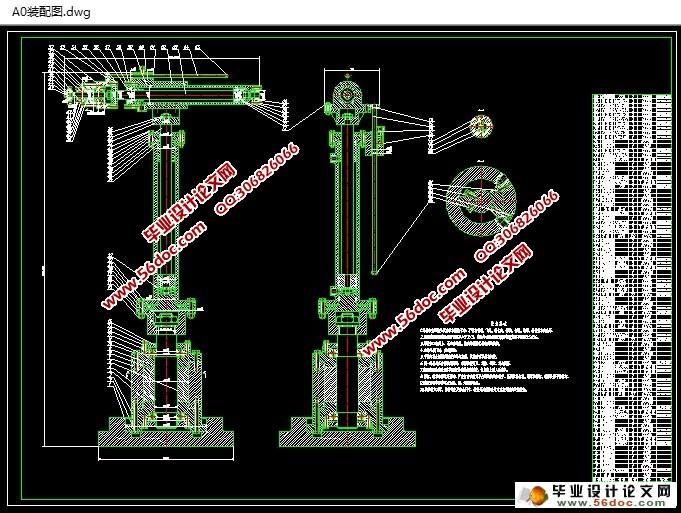
焊接机械手的传动机构与控制系统设计(含CAD零件图装配图液压图)(设计说明书15000字,CAD图9张,答辩PPT)
摘要
在工业生产中,有不少工作会对工人身体产生不良影响,例如焊接工作。而焊接却是生产中必不可少的环节。随着科技的发展和工业需求的增加,焊接技术在工业生产中所占据的分量越来越大,而且焊接技术的优良程度直接影响着零件或产品的质量。国内焊接机器人应用虽已具有一定规模,但与我国焊接生产总体需求相差甚远。因此,大力研究并推广焊接机器人技术势在必行。
为了设计出可以投入生产应用的焊接机械手,通过查阅了相关参考资料,了解了国内外焊接机械手的发展现状,掌握了机械手的基本工作原理,进而对机械手传动机构进行设计计算和强度校核,利用CAD绘图软件绘制出结构图,并对液压驱动系统进行了仿真,最终设计出基本可投入生产应用的焊接机械手。
关键字:焊接机械手;机械机构设计;控制系统设计
Design of Welding Manipulator Transmission Mechanism and Control System
ABSTRACT
In industrial production, there are a lot of work have the harmful effect on the workers’ health such as welding. But welding is necessary in production. With the development of technology and the increase in industrial demand, welding in industrial production occupied more and more weight, and excellent welding technology directly affects the degree of the quality of parts or products. Although the domestic application of welding robot with a certain scale, but falls far short of the overall demand for welding. Therefore, vigorously research and the promotion of welding robot technology are imperative.
In order to design a welding manipulator that can put into production application, through consulting the related reference material, understand the current situation of the welding manipulator’s development on the domestic and foreign, and master the basic working principle of the manipulator. Then design calculation and intensity of manipulator transmission mechanism, use CAD drawing software rendering the structure, and simulate the hydraulic drive system, and finally designed a welding manipulator that can be worked in production application.
Key words: welding manipulator; Mechanism design; Control system design
主要研究内容
工业机械手在国民生产中有广泛的应用,许多机械设备都用到工业机械手,它是近代自动控制领域内出现的一种新型的技术装备。本次设计的工业机械手设备简单,动作灵活,经济实用,稳定性好,适于使用。
在研究了国内外机械手发展的现状,通过学习机械手的工作原理,熟悉了机械手的运动机理。在此基础上,确定了焊接机械手的基本系统结构,对焊接机械手的运动进行了简单的力学模型分析,完成了机械手传动机构和简单的控制系统方面的设计工作。

目录
1绪论 1
1.1技术概述 1
1.2机械手的发展历程 1
1.3机械手在生产中的应用 2
1.4主要研究内容 2
2总体方案设计 4
2.1设计要求 4
2.2机械手的基本形式 4
2.3机械手的组成 5
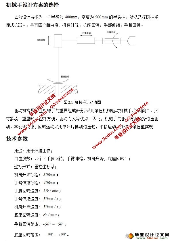
2.4机械手设计方案的选择 5
2.5技术参数 6
3腕部结构的设计计算 7
3.1腕部设计的基本要求 7
3.2腕部的结构及选择 7
3.3腕部液压缸的设计计算 8
3.3.1腕部驱动力计算 8
3.3.2液压缸缸盖螺钉计算 10
3.3.3动片及定片的连接螺钉计算 11
3.4腕部液压缸轴承的计算 12
3.5其他零部件的选择 13
4手臂结构的设计计算 14
4.1手臂设计的基本要求 14
4.2手臂的结构及选择 14
4.3手臂液压缸的设计计算 15
4.3.1手臂工作负载 15
4.3.2液压缸内径的计算 16
4.3.3活塞杆的计算 16
4.3.4液压缸缸筒壁厚计算 17
4.3.5液压缸稳定性校核 18
4.3.6连接部件的强度计算 20
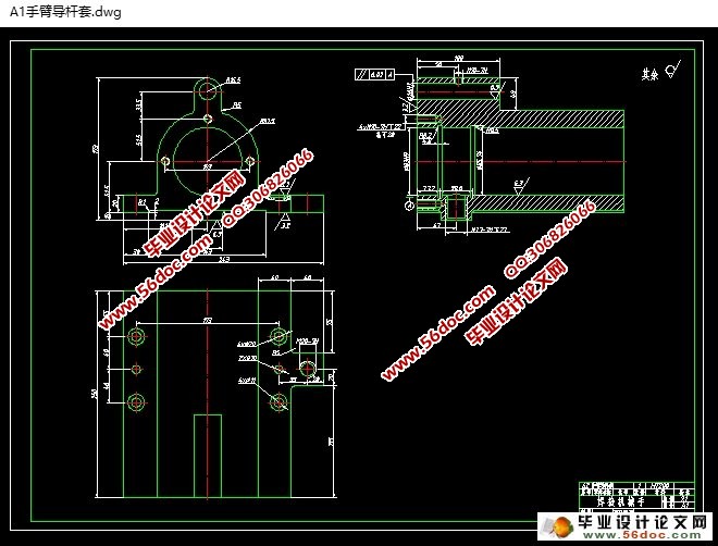
4.4手臂导杆的设计计算 20
4.5其他零部件的选择 21
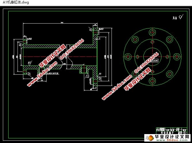
5机身结构的设计计算 23
5.1机身设计的基本要求 23
5.2机身的结构及选择 23
5.3机身升降液压缸的设计计算 24
5.3.1升降液压缸工作负载 24
5.3.2升降液压缸内径的计算 25
5.3.3升降液压缸不自锁的条件分析 25
5.3.4升降液压缸活塞杆的计算 27
5.3.5升降液压缸缸筒壁厚计算 28
5.3.6升降液压缸稳定性校核 28
5.3.7连接部件的强度计算 30
5.4机身摆动液压缸的设计计算 32
5.4.1摆动液压缸驱动力计算 32
5.4.2摆动液压缸缸盖螺钉计算 34
5.4.3动片及定片的连接螺钉计算 36
5.5机身摆动液压缸轴承的计算 37
5.6机身导杆的设计计算 37
5.7其他零部件的选择 38
6液压系统设计 39
6.1设计的基本要求 39
6.2系统总体设计方案 39
6.3液压系统的设计计算 40
6.3.1流量的计算 40
6.3.2液压泵的设计 41
6.3.3液压泵型号的选择 41
6.3.4液压泵电机的确定 42
6.3.5油箱的容量计算 42
6.4液压系统图 43
6.5液压系统工作原理 43
6.6电气控制图 44
总结 45
参考文献 46
致谢 47
附录A 48
附录A
图纸清单
序号 图纸名称 图纸大小 备注
1 机械手总装配图 A0
2 机身缸体 A1
3 手臂导杆套 A1
4 机身导杆套 A2
5 机身托盘 A2
6 机座回转轴 A2
7 手臂托盘 A2
8 手腕回转轴 A3
|
