高楼逃生器逃生装置设计(含CAD零件图装配图)(论文说明书7500字,CAD图7张)
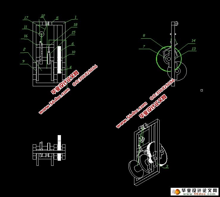
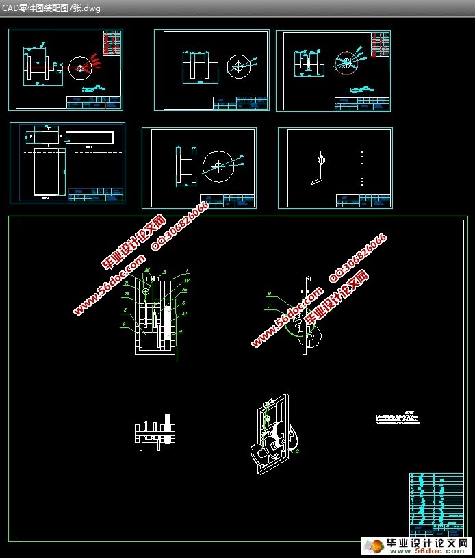
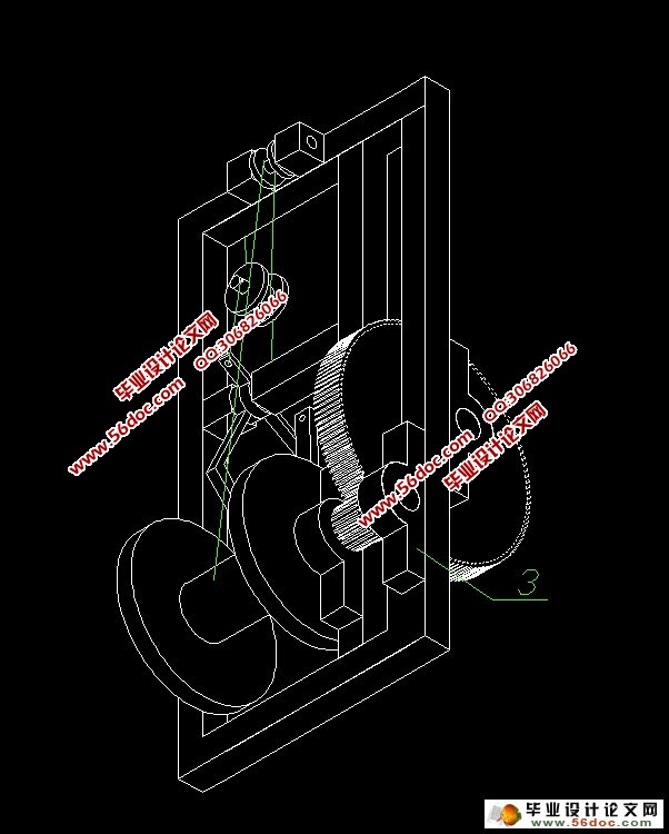
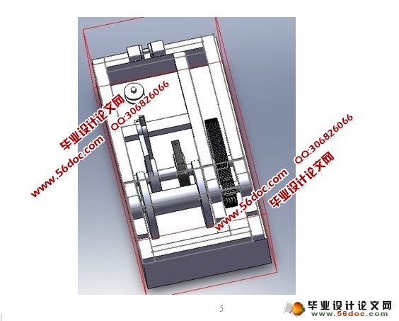
摘 要:本设计涉及一种高楼逃生器,包括机架、以及安装在机架上的升降机构、传动机构、控制机构、救生斗;升降机构包括滚轮、绳索、滑轮的对称的两组;传动机构对称安装在机架且与升降机构相匹配的第一齿轮副和第二齿轮副,该第一、第二齿轮副之间通过第三齿轮副联接,第三齿轮副包括安装在机架的总传动轴和三个扇形齿轮;控制机构包括凸轮拨杆滑块机构和包括刹车毂的刹车机构,凸轮刹车毂均安装在总传动轴上。本发明利用自重实现运送装置的下降与上升,速度快,下降速度得到有效保证,稳定性高,操作简单。
关键词:升降机构;传动机构;控制机构;救生斗;
Design of high-rise evacuation
Abstract: The design involves a high-rise escape device, including the rack, and installation of the rack on the elevator, transmission, control agencies, rescue bucket; lifting mechanism including the wheel, ropes, pulleys, the symmetry of the two groups; transmission symmetrical rack and with the lifting mechanism to match the first and second gears gear pair, the first and second gears connected between the gear pair through the third, the third rack gear pair including the total shaft and three fan-shaped gear; control agencies include the slider cam lever bodies and agencies including the brake drum brake, brake hub cam shaft are installed on the total. Of the present invention to achieve delivery of devices using weight decreased with increasing speed, the rate of decline has been effectively guaranteed, high stability, simple operation.
Keywords: lifting mechanism; transmission; control agencies; rescue bucket;
逃生装置在摩擦系数一定的情况下,当装置下方负载G增加时,相应装置悬挂端的拉力增加,与负载近似相等;利用杠杆原理,装置两端摩擦片所受正压力F也增大,摩擦片与定位转子发生摩擦而产生的摩擦阻力也相应增加,以保证下落近似匀速,从而使逃生者可以在不大于5m / s安全的速度着陆。当负载减小时也同理。同时,逃生装置还设置了手动探制装置,使逃生者的下降速度可以手动控制,逃生者的安全得以保证。


目 录
摘 要: 3
关键词: 3
1 前言 4
2 国内外研究现状 4
3 设计思路 5
4 工作原理 5
5 创新点 5
6 传动装置的总体设计 5
6.1拟定传动方案 5
6.1.1分析传动系统的工作情况 5
6.1.2传动装置简图: 5
6.2滚轮的设计 7
6.2.2滚轮的效率: 7
6.3计算传动装置总传动比 7
6.4计算传动装置的运动和动力参数 7
6.4.1各轴转速 7
6.4.2各轴输入功率 7
6.4.3各轴转矩 7
6.5传动零件的设计计算 8
6.5.1齿轮设计计算及校核 8
6.2轴的设计(高速轴) 13
6.2.1初步确定轴的最小直径 13
6.2.2轴的结构设计(参考机械设计教材图15-26及其例题) 14
6.2.3确定轴上圆角和倒角尺寸 14
6.2.4求轴上的载荷 14
6.2.5按弯扭合成应力校核轴的强度 15
6.2.6精确校核轴的疲劳强度 16
6.3减速器的箱体和附件 18
6.4滚动轴承的选择和强度校核 18
6.4.1初选轴承 18
6.4.2轴承使用寿命的计算 18
6.5刹车机构的计算 19
6.5.1自动刹车机构的计算 19
6.5.2手动刹车机构的设计与计算 19
6.6设计小结 20
参 考 文 献 21
致谢 22
|


