支板的冲压工艺与模具设计(任务书,中期检查表,论文说明书10000字,工艺过程卡,CAD图13张)
摘 要
本设计题目为复合模具设计,采用典型倒装复合模具设计。通过工艺分析,工艺方案的确定,确定了模具设计的方向;通过对支板零件尺寸的分析,确定了毛坯尺寸,计算冲裁力,来计算压力中心,选择压力机和压力机的吨位。
本设计运用了冲裁工艺及模具设计的专业知识。首先,通过分析制件的结构工艺,去选择模具的类型;然后,分析了制造制件所用的材料进而确定凸凹模的尺寸,也为凸、凹模的材料及压力机选择提供有了依据。最后经过总体分析冲裁件的特征,确定了模具设计参数,选择其他零件及卸料装置。
关键词: 凸凹模 凸模 凹模
Support plate stamping process and die desigen
ABSTRACT
The design for the complex subject of mold design, using a typical flip-complex mold design. Through process analysis, process identification program to determine the direction of the mold design; through parts of the support plate size analysis, to determine the rough size, calculating punching power, to calculate the pressure center, select the tonnage presses and presses.
The use of blanking process design and die design expertise. First, by analyzing the parts of the structure of technology, to choose the type of mold; then, analysis of manufacturing parts of the material used to determine the size of convex and concave mold, as well as convex, concave mold and the material selection has been based on press. After blanking the final pieces of the overall analysis of the characteristics of the mold to determine the design parameters, choose the other parts and discharge devices 。
Keywords: Bump Die Die Punch
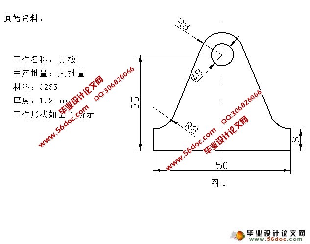
冲裁件为Q235钢,是碳素结构钢,强度较高。零件外形简单,结构对称,是由圆弧和直线组成的。冲裁件内外形所能得到的经济精度为IT7~IT14,孔中心与边缘距离尺寸公差为 。将以上精度与零件的精度要求相比较,可以认为该零件的精度要求能够在冲裁加工中得到保证,其他尺寸标注、生产批量等也均符合冲裁的工艺要求,故决定采用冲压方式进行加工。


目 录
绪论……………………………………………………………………………………1
国内模具的现状……………………………………………………………………1
国内模具的发展趋势………………………………………………………………2
国外模具的现状和发展趋势………………………………………………………3
1. 冲孔落料件工艺分析………………………………………………………………6
2.冲孔落料件工艺方案的确定………………………………………………………7
3. 必要的工艺计算……………………………………………………………………8
3.1 排样设计………………………………………………………………………8
3.2 凸、凹模刃口尺寸计算………………………………………………………9
3.2.1冲孔 mm凸凹模刃口尺寸的计算……………………………………9
3.2.2外形落料凸、凹模刃口尺寸的计算……………………………………9
3.3 冲裁力的计算…………………………………………………………………11
3.4 压力中心的确定……………………………………………………………11
4. 模具的总体设计 …………………………………………………………………13
5.模具主要零部件的设计……………………………………………………………14
5.1 凸模、凹模的结构设计………………………………………………………14
5.1.1 落料凸、凹模的结构设计………………………………………………14
5.1.2 推件块的设计……………………………………………………………15
5.1.3 冲孔 mm凸模的结构设计……………………………………………16
5.1.4 凸凹模结构的设计………………………………………………………16
5.2 落料弹性元件的设计…………………………………………………………17
5.3 模架的设计……………………………………………………………………18
6. 冲压设备的选定……………………………………………………………………20
7. 绘制模具总装图……………………………………………………………………22
结束语…………………………………………………………………………………24
致谢……………………………………………………………………………………26
参考文献………………………………………………………………………………27
插图清单
1.支板零件图 ………………………………………………………………………… 6
2.排样图 ……………………………………………………………………………… 9
3.落料凹模示意图……………………………………………………………………10
4.压力中心的确定 ……………………………………………………………………12
5.凹模…………………………………………………………………………………15
6.推件块示意图………………………………………………………………………16
7.凸凹模结构示意图…………………………………………………………………17
8.弹性体示意图………………………………………………………………………18
9.开式双柱可倾式压力机型号和技术参数图………………………………………20
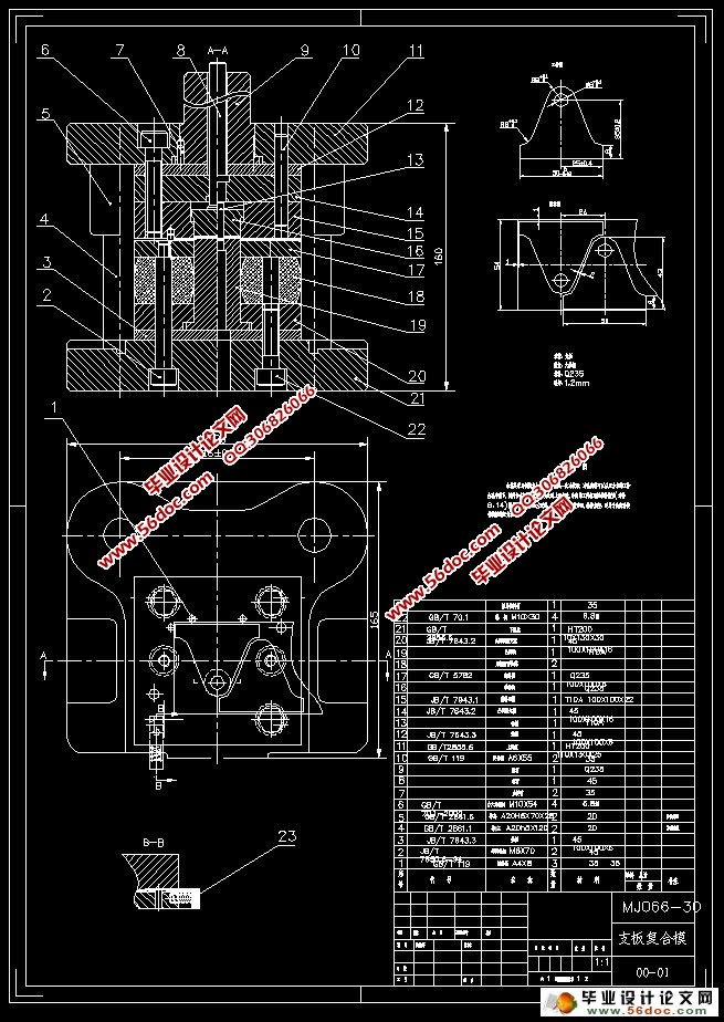
10.模具总装示意图………………………………………………………………… 22
|


