冲压弯曲级进模设计(含CAD零件图装配图)(文献综述,设计说明书10200字,CAD图5张,实习报告)
摘 要
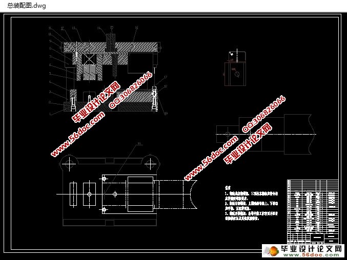
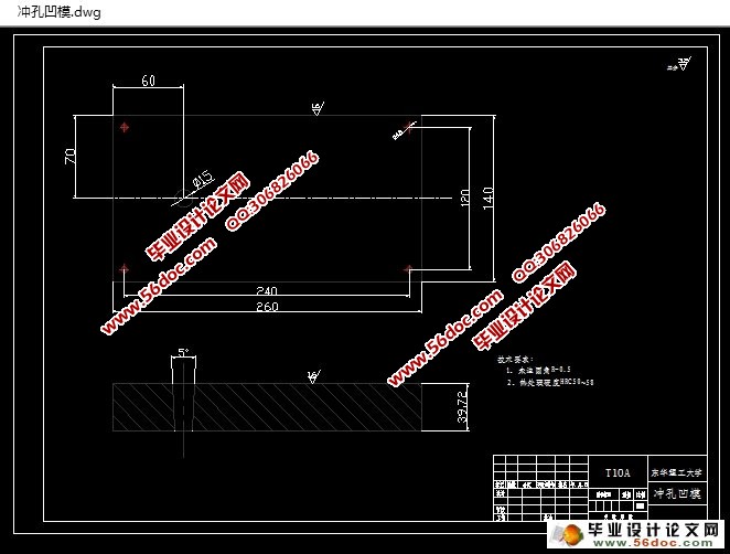
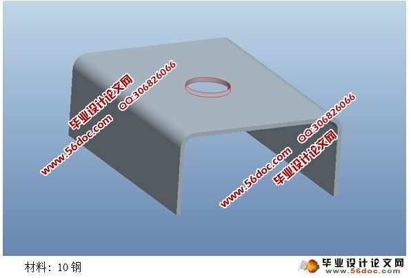
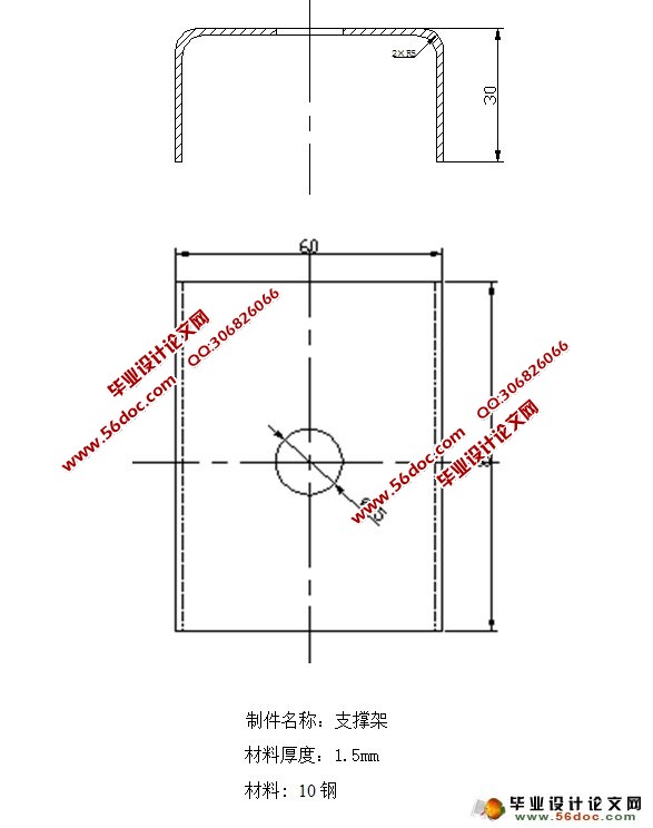
本论文设计的是一个U型件支承架,其设计的基本步骤是冲孔、不完全落料、弯曲、落料的的冲压模具设计过程。 我们在对制件进行了通过冲压工艺分析,以及结合考虑产品的质量要求和生产实际因素,确定了最佳工艺方案为冲孔-不完全落料-弯曲-落料,并且对模具进行了设计和分析论证。设计过程也是充分利用冷冲模国家标准和典型结合,大大提高了模具设计效率,符合当代模具设计要求,在最后我们通过对模具的主要零部件的加工工艺过程和装配工艺也进行了详细的介绍。整个过程采用AutoCAD 软件绘制模具的二维装配图和零件图,然后利用UG软件进行冲压模具设计,设计全部模具,零件,完成装配。
关键词:级进模、 多工位、 AutoCAD、 装配
ABSTRACT
This thesis design is a u-shaped support frame, the design is the basic step of punching and incomplete blanking, bending and blanking punching die design process. We are in the product were analyzed by stamping process, and considering the quality of the product requirements and actual production factors, to determine the optimum solution for punching - incomplete blanking bending - blanking, and on the mold design and analysis. Design process is also make full use of the cold die national standard and typical combination, greatly improve the efficiency of the mold design, meet the demands of contemporary mold design, and at last we through the processing technology of main components of the mold and assembly process also has carried on the detailed introduction. The whole process using AutoCAD software rendering the mold 2 d assembly drawing and part drawing, and then using UG software to design stamping die design in the mold, parts, finished assembly.
Keywords: progressive die, transfer, AutoCAD, assembly
目 录
1. 绪论 1
第一章 冲裁弯曲件的工艺分析 2
第二章 确定工艺方案和模具的结构形式 4
第三章 模具总体结构设计 5
3.1 模具类型的选择 5
3.2 卸料方式的选择 5
3.3 导向方式的选择 5
3.4 定位方式的选择 5
第四章 模具设计工艺计算 6
4.1 计算毛坯尺寸 6
4.2 毛坯排样设计 7
第五章 冲裁力的计算 8
5.1 计算冲裁力的公式 8
5.2 总的冲裁力计算 8
第六章 冲裁间隙的确定 13
第七章 主要零部件设计 15
7.1 刃口尺寸计算的基本原则 15
7.2 刃口尺寸的计算 15
7.3 冲孔凹模 16
7.4 冲孔凸模 16
7.5 凹凸模 17
7.6 弯曲凸模 18
7.7 定位零件的相关设计 18
7.8 卸料零件的相关设计 18
第八章 模具总装配 21
第九章 总结 23
致 谢 24
参考文献 25
|


