焊片冲压成形工艺及模具设计(含CAD零件图装配图)(任务书,中期检查表,论文说明书15000字,工艺卡,工序卡,CAD图11张)
摘要:本设计题目为复合模具设计,体现了典型复合模具设计的要求,内容与方向。通过工艺分析,工艺方案的确定,确定了模具设计的方向, 对毛坯尺寸的确定,计算冲裁力,来计算压力中心,选择压力机和压力机的吨位。复合模是指冲床在一次行程中,完成落料、冲孔等多个工序的一种模具结构。相对其他冷冲压模具结构而言,它具有以下一些优点:①工件同轴度较好,表面平直,尺寸精度较高; ②生产效率高,受条料外形尺寸的精度限制较小。但需考虑的问题是:模具零部件加工制造比较困难,成本较高,并且凸凹模容易受到最小壁厚的限制。
本设计运用了冲裁工艺及模具设计的基础知识。首先,分析了板材的性能要求,为选去模具的类型做了准备,同时,也为凸,凹模的材料有了依据。后分析冲裁件的特征,确定了模具设计参数,选择其他零件及卸料装置。也为凸,凹模尺寸的计算有了根据。还有零件的加工工艺。
关键词: 复合模 工艺性能 凸凹模 模具制造
Soldering lug ramming superposable die design
Abstract: This design topic designs for The piercing die design of the dunnage backup plate, body now typical model The piercing die design of request, contents and direction.Pass the craft analysis, the craft project really settles, making sure the direction of The piercing die design, really settling to the blank product size, computing to the blanking pressure, compute the pressure center, choose the tonnage of the pressure machine and the pressure machine. The compound mold mean the punching machine is in a route of travel, completing to fall to anticipate, a kind of molding tool structure of several work prefaces of etc. of blunt bore.Opposite and other cold hurtle to press the molding tool structure but speeches, it has following some advantageses:The ① work piece is together the stalk degree is better, the surface is straight and even, the size accuracy is higher; The ② produces the efficiency high, be subjected to the anticipates the shape size of accuracy limit smaller.But need the problem of the consideration is:The molding tool zero partses process the manufacturing more difficulty, the cost is higher, and the convex and cave mold is subjected to the thick restrict of minimum wall easily.
This design made use of to hurtle foundation knowledge of blanking craft and The piercing die design. First, Analyzed the function request of the plank material, did preparation for the type that chooses to the die, is also convex, in the meantime, the material of punch and cavitydie had a basis.Analyze to hurtle a characteristic of cut the piece behind, make sure the molding tool design parameter, choose other spare partses and unload to anticipate device.Is also convex, the calculation of the cave mold size had a basis.Still there is spare parts to process a craft.
Keywords:Compound mold craft function The convex and cave mold molding tool manufacturing
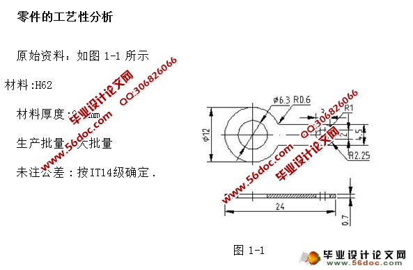
该零件材料为H62(黄铜)结构简单,形状对称,是由圆弧和直线组成的。冲孔时有尺寸为φ6.3 根据课本知冲孔时,因受凸模强度的限制,孔的尺寸不应太小.冲孔的最小尺寸取决于材料性能,凸模的强度和模具结构等.根据表3-3可查得圆形孔最小值得d=0.9t=0.9×0.7=0.63mm<φ6.3所以满足工艺性要求.
冲裁件孔与孔之间:孔与边缘之间的距离受模具的强度和冲裁件质量的制约,其值不应过小,一般要求C≥(1~1.5)t,C′>(1.5~2)t所以经分析计算可知孔与孔之间距离满足工艺性要求,可以用冲裁进行加工。
目 录
1 绪论…………………………………………………………………………………1
1.1冲压的概念、特点及应用………………………………………………………1
1.2冲压的基本工序及模具…………………………………………………………2
1.3冲压技术的现状及发展方向……………………………………………………3
2 制件的工艺性分析…………………………………………………………………7
2.1零件的工艺性分析…………………………………………………………………7
2.2冲裁件的精度与粗糙度…………………………………………………………7
2.3冲裁件的材料………………………………………………………………………8
2.4确定工艺方案………………………………………………………………………8
3 冲压模具总体结构设计……………………………………………………………9
3.1模具类型…………………………………………………………………………9
3.2操作与定位方式…………………………………………………………………9
3.3卸料与出件方式…………………………………………………………………9
3.4模架类型及精度…………………………………………………………………9
4 冲压模具工艺与设计计算…………………………………………………………10
4.1排样设计与计算…………………………………………………………………10
4.2设计冲压力与压力中心,初选压力机…………………………………………12
4.2.1冲裁力…………………………………………………………………………12
4.2.2压力中心………………………………………………………………………14
4.2.3计算凸凹模刃口尺寸及偏差…………………………………………………14
5 模具的总装图与零件图……………………………………………………………18
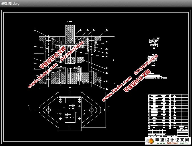
5.1根据前面的设计与分析,我们可以得出如级进模具的总装图如附图所示…18
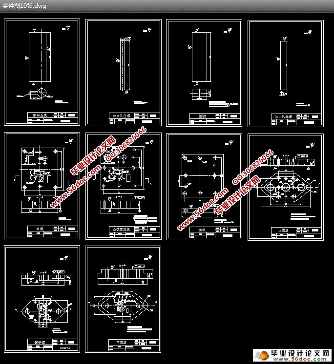
5.2冲压模具的零件图………………………………………………………………18
5.2.1凹模设计………………………………………………………………………18
5.2.2凸模设计………………………………………………………………………20
5.2.3选择坚固件及定位零件………………………………………………………23
5.2.4设计和选用卸料与出件零件…………………………………………………25
5.2.5选择模架及其他模具零件……………………………………………………26
5.3压力机及闭合高度的校核………………………………………………………28
结论……………………………………………………………………………………29
致谢 …………………………………………………………………………………30
参考文献………………………………………………………………………………31
插表清单
表1 机械加工工艺过程卡……………………………………………………………附表一
表2 机械加工工序卡…………………………………………………………………附表二
插图清单
图1-1 工件图……………………………………………………………………… 7
图4-1 排样图………………………………………………………………………11
图4-2 压力中心……………………………………………………………………14
图5-1 凹模 ………………………………………………………………………19
图5-2 凸模…………………………………………………………………………22
图5-3 固定挡料销…………………………………………………………………23
图5-4 始用导料销…………………………………………………………………24
图5-5 始用导料销弹簧芯柱………………………………………………………24
图5-6 导料板………………………………………………………………………25
图5-7 导正销………………………………………………………………………25
图5-9 卸料板………………………………………………………………………26
图5-10 模柄……………………………………………………………………… 27
|
