角片套冷冲压工艺及级进模设计(含任务书,开题报告,外文翻译,毕业论文说明书29000字,进度检查表,CAD图纸7张)
摘 要
本模具采用切废料方式进行冲压,模具结构采用切口、拉深、冲导正孔、导正再拉深、切废料、弯曲、切断的工序设计,排样采用单排横排排列。并采用正装方式设计模具结构,即凹模装在下模部分,同时为了正确控制送料步距采用单侧侧刃定距,在主要位置采用导正销导正精确定位。由于料较薄,冲压速度较快,卸料可采用弹性卸料结构,建议弹性材料采用弹簧。废料采用在凹模(下模)向下推出,最后产品也是在下模向下推出。带料采用自动左右有侧压的送料装置。同时为了正确控制送料步距采用侧刃定距。由于料不是很厚,冲压速度适中,故卸料采用弹性卸料结构,弹性材料采用矩形截面弹簧。废料和产品均采用向下推出。带料采用自右向左的自动送料装置。
冲压工艺分析主要考虑产品的冲压成形工艺,最主要的是包括技术和经济两方面内容。在技术方面,根据产品图纸,主要分析零件的形状特点、尺寸大小、精度要求和材料性能等因素是否符合冲压工艺的要求;在经济方面,主要根据冲压件的生产批量,分析产品成本,阐明采用冲压生产可以取得的经济效益。因此工艺分析,主要是讨论在不影响零件使用的前提下,以最简单最经济的方法冲压出来。
关键词:角片套;冲压工艺;排样;级进模
Abstract
The die by cutting waste stamping, die structure incision, drawing, red pilot hole, drawing guide, cut waste, bending, the cut process design, arranged in a single row of horizontal nesting.And dress design the die structure, the die attached to the lower die part, in order to properly control the feeding step unilateral side of the blade fixed pitch, in the main location pilots to precise positioning.As the material is thin, stamping speed, the discharge may be used in the elastic unloading structure, it is recommended that the elastic material with spring. Waste using the die (down die) launched down the final product is lower die down soon.Strip automatic feeding device left and right side pressure. In order to properly control the feeding step away from the side of the blade fixed pitch. As the material is not very thick, stamping moderate speed, the discharge elastic unloading structure, elastic material with rectangular cross-section spring.The waste products are used down soon.Automatic feeding device with material from right to left.
Stamping process analysis consider the stamping process, most notably including the technical and economic aspects.On the technical side, according to the product drawings, mainly analyzes the characteristics of the shape of parts, size, accuracy requirements and material properties and other factors meets the requirements of the stamping process;In economic terms, mainly based on the production volume of the stampings, analyze the cost of the product, and clarify the use of the stamping production can be achieved economic benefits.Process analysis, mainly to discuss stamping out does not affect the part of the premise, the simplest and most economical way.
Key words: Angle piece sets; Atamping process; Nesting;Progressive die
课题研究的主要内容
1.制件工艺分析和工艺方案制定
a)冲裁件的工艺分析:本次毕业设计的零件对冲裁工艺有良好的适应性,故采用冲裁工艺。
b)工艺方案制定:根据毕业设计任务书的要求,本次冲裁工艺方案采用落料冲孔复合模。
2.必要的工艺计算
对冲裁件的尺寸大小,精度要求进行相关计算。
3.模具结构分析与设计;
模具的结构分析与设计包括工作部分,模架,冲模的辅助装置与辅助机构,横向冲压机构。
4.模具主要零件设计及有关尺寸计算;
模具主要零件设计计算包括工作零件,定位零件,压料、卸料及出件零件,导向零件,固定零件,紧固及其他零件。
目 录
摘 要 III
ABSTRACT IV
目 录 V
1 绪 论 1
1.1 课题研究的目的和意义 1
1.2 课题国内外研究概况 1
1.2.1 国外模具发展概况 1
1.2.2 国内模具发展概况 2
1.3 课题研究的主要内容 3
2 冲压工艺设计 4
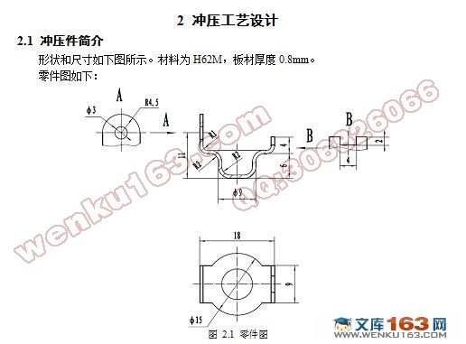
2.1 冲压件简介 4
2.2 冲压的工艺性分析 5
2.3 冲压工艺方案的确定 7
2.3.1 冲压模具类型 7
2.3.2 冲压工艺分析和计算 8
2.3.3 工序汇总 14
3 角片套连续模设计 15
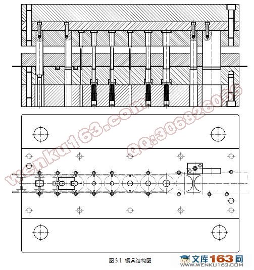
3.1 模具结构 15
3.2 确定其搭边值 16
3.3 确定排样图 16
3.3.1 送料步距与带料宽度 16
3.3.2 排样方案 18
3.4 材料利用率计算 18
3.5 凸、凹模等刃口尺寸的确定 19
3.5.1 侧刃、侧刃凹模刃口尺寸计算 19
3.5.2 切口凸、凹模刃口尺寸计算 20
3.5.3 第1次拉深凸、凹模工作部分尺寸及其公差 21
3.5.4 第2次拉深凸、凹模工作部分尺寸及其公差 22
3.5.5 第3次拉深凸、凹模工作部分尺寸及其公差 22
3.5.6 拉深整形凸、凹模工作部分尺寸及其公差 23
3.5.7 导正孔凸、凹模刃口尺寸及其公差 23
3.5.8 冲圆孔凸、凹模刃口尺寸及其公差 24
3.5.9 切废料凸、凹模刃口尺寸及其公差 25
3.5.10 切断凸、凹模刃口尺寸及其公差 26
3.5.11 弯曲凸、凹模工作部分尺寸计算 27
3.6 冲压力计算 29
3.6.1 侧刃冲压力 29
3.6.2 冲切口部分冲压力 29
3.6.3 拉深部分冲压力 30
3.6.4 冲导正孔冲压力 31
3.6.5 整形部分冲压力 32
3.6.6 冲圆孔冲压力 32
3.6.7 切废料部分冲压力 32
3.6.8 切断部分冲压力 33
3.6.9 弯曲部分冲压力 33
3.6.10 总冲压力 34
3.7 压力机选用 34
3.8 压力中心计算 35
3.9 模具主要零部件的结构设计 35
3.9.1 凹模结构及设计 35
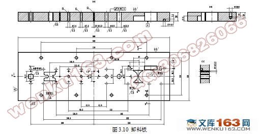
3.9.2 卸料板设计 37
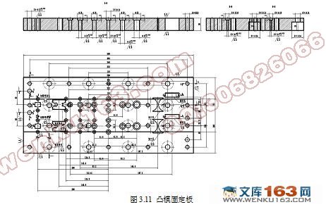
3.9.3 凸模固定板设计 38
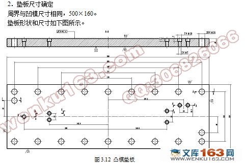
3.9.4 凸模垫板设计 39
3.9.5 切口凸模的结构设计 39
3.9.6 第1次拉深凸模设计 40
3.9.7 第2次拉深凸模设计 40
3.9.8 第3次拉深凸模设计 41
3.9.9 整形凸模设计 42
3.9.10 侧刃设计 42
3.9.11 侧刃挡块设计 43
3.9.12 导正冲孔凸模设计 44
3.9.13 切废料凸模的结构设计 44
3.9.14 切断弯曲凸模的结构设计 45
3.9.15 导正钉设计 46
3.10 标准件确定 46
3.10.1 模架确定 46
3.10.2 上模螺钉确定 47
3.10.3 上模销确定 47
3.10.4 下模螺钉确定 48
3.10.5 下模销确定 48
3.10.6 卸料螺钉确定 48
3.10.7 卸料弹簧设计 48
3.10.8 拉深顶件弹簧设计 48
3.10.9 抬料销确定 49
3.10.10 抬料销弹簧设计 49
3.10.11 凸模固定螺钉确定 49
3.10.12 挡块固定螺钉确定 49
3.10.13 挡块销确定 49
3.11 模具闭合高度、校验压力机 49
4 结论与展望 51
致 谢 52
参考文献 53
|